KMD–5210 Installation and Operation
Revision E
13
SECTION 2
Installation
This section provides important instructions and guidelines for
installing the KMD-5210 LAN Controller. Carefully review this
information prior to installation.
Mounting
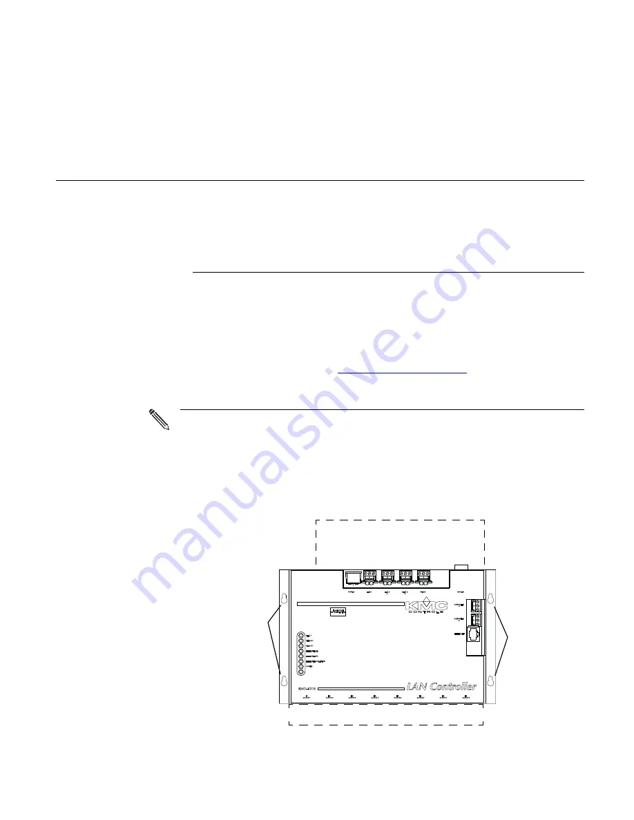
Mount the controller inside of a metal enclosure. KMC Controls recommends
using a UL-approved Enclosed Energy Management Equipment Panel such as
a KMC model HCO–1034, HCO–1035 or HCO–1036. Insert #6 or #8 hardware
through the two mounting holes on each side of the controller to securely
fasten it to a flat surface. See
locations and dimensions. To maintain RF emission specifications, use either
shielded connecting cables or enclose all cables in conduit.
Note
Provide sufficient clearance around the controller for cables and wiring.
◆
Allow a minimum of 3 inches (7.6 cm) of clearance at the top edge of the
controller for the power and modem connectors.
◆
Allow a minimum of 1.5 inches (3.8 cm) of clearance for the ribbon cables
at the bottom of the controller.
Illustration 2-1 Mounting details
Allow 1.5 in. (3.8 cm) for cables
Allow 3.0 in. (7.6 cm) for cables
Mounting
holes
Mounting
holes
Summary of Contents for KMD-5210
Page 4: ...KMC Controls Revision E 4 ...
Page 12: ...KMC Controls Revision E About the LAN controller Safety Considerations 12 ...
Page 26: ...KMC Controls Revision E Installation Connecting to a Computer 26 ...
Page 30: ...KMC Controls Revision E Operation Resetting the controller 30 ...
Page 38: ...KMC Controls Revision E Configuration and programming System time keeping 38 ...


