
KMD-5575
3
Installation and Operation Guide
Important Notices
©2008 KMC Controls
The KMC logo is a trademark of KMC Controls, Inc. All rights reserved.
No part of this publication may be reproduced, transmitted, transcribed,
stored in a retrieval system, or translated into any language in any form by
any means without the written permission of KMC Controls, Inc. Printed in
U.S.A.
Disclaimer
The material in this document is provided for information purposes only. The
contents and the product(s) described herein are subject to change without
notice. KMC Controls, Inc. makes no representations or warranties with
respect to this document. In no event shall KMC Controls, Inc. be liable for
any damages, direct or incidental, arising out of or related to the use of this
document.
KMC Controls
P.O. Box 497
19476 Industrial Drive
New Paris, IN 46553
U.S.A.
TEL: 574.831.5250
FAX: 574.831.5252
E-mail: info@kmccontrols.com
Introduction
The KMC KMD-5575 Network Repeater-Isolator extends and reconditions
EIA-485 network communications as well as enabling “T” or branch networks.
The KMD-5575 is designed to recondition a degraded EIA-485 (formerly RS-485)
communication signal on a KMC KMDigital or BACnet subnetwork. Two primary
factors that cause communication signal degradation within the digital subnet
-
work are long subnetwork wiring lengths and the number of digital controllers
connected to the subnetwork.
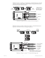
A KMD-5575 is required after every 31 consecutive controllers on KMDigital or
BACnet subnetworks (e.g., between controllers 31 and 32) or if the cumulative
wiring distance exceeds 4,000 feet. (For smoke control applications, the maximum
total length of the EIA-485 network cable, including all repeaters, is 4,000 feet.)
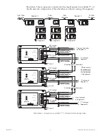
In addition, the KMD-5575 is required for “T” or branch network wiring configu
-
rations (see Illustration 4 ).
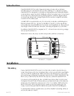
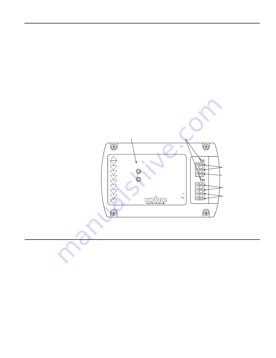
Illustration 1 shows the major module components and their connections.
Illustration 1—Components
Status LEDs
Network 2
Connections
Network 1
Connections
Power
Connection
EOL Terminations
Circuit Ground
Repeater
KMD-5575
STATUS
2
1
EOL
A
B
GND
EOL
A
B
NETWORK-2
NETWORK-1
24 VAC
NETWORK-1 & 2
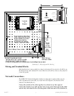
Installation
Mounting
Fasten the KMC KMD-5575 securely to a flat surface inside a metal enclosure
using #6 hardware in the four mounting holes on the top and bottom (see Illustra
-
tion 2). For HVAC applications, KMC Controls recommends using a UL Listed
enclosed energy management equipment panel such as a KMC model HCO-1034,
HCO-1035, or HCO-1036. The HCO-1102 enclosure will hold one KMD-5575.
For smoke control applications, the controller must be mounted in a UL Listed
Firefighter’s Smoke Control Station enclosure or listed enclosure with minimum
dimensions. The minimum enclosure size is 16 x 18 x 6 inches. KMC enclosures
HCO-1034, HCO-1035, and HCO-1036 are approved for this application. See
Smoke Control Manuals 000-035-08 (BACnet) and/or 000-035-09 (KMDigital).
To maintain RF emission specifications, use either shielded connecting cables or
enclose all cables in conduit.


