KMD-5575
5
Installation and Operation Guide
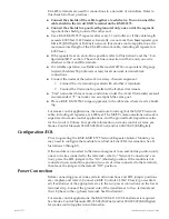
Illustration 3—Repeater at End of Line Between Two Network Segments
EOL Jumpers Installed
A
B
A
B
24 VAC
Shields Not Connected
Repeater
KMD-5575
STATUS
2
1
EOL
A
B
GND
EOL
A
B
NETWORK-2
NETWORK-1
24 VAC
NETWORK-1 & 2
Shield Grounded at One End*
Segment Y
Segment X
*Shields should be
connected to an earth
ground at only one
end of the segment
Segment Y
Segment X
Other
Controllers
Other
Controllers
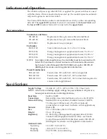
Illustration 4 shows a repeater connected in a single “T” or branch network con
-
figuration. (One branch is shown coming off a segment.)
Illustration 4—Repeater in a single “T” or Branch Sublan Configuration
~
24 VAC
A “T” or Branch
B Segment Y
A Previous Controller
B on Segment X
A Next Controller
B on Segment X
EOL Jumper
Removed
EOL Jumper
Installed
Shield Grounded*
Shields Connected
*
Shields should be connected to an earth
ground at only one end of the segment
Repeater
KMD-5575
STATUS
2
1
EOL
A
B
GND
EOL
A
B
NETWORK-2
NETWORK-1
24 VAC
NETWORK-1 & 2
Repeater
KMD-5575
STATUS
2
1
EOL
A
B
GND
EOL
A
B
NETWORK-2
NETWORK-1
24 VAC
NETWORK-1 & 2
From Other
Controllers
To Other
Controllers
Segment Y
Segment X
Illustration 3 shows a repeater as it might appear connected between two network
segments at the End-of-Line (EOL) position. (See the Configuration/EOL section
for information about the EOL jumper.)


