SECTION 7
HIGH PRESSURE WATER
May 2003
p. 7-4
49831951
CAUTION
!
CAUTION
!
7.2.2
HP Cylinder “Jug” (HP Cyl., Sealing Head, Flanges, & Studs)—
Disassembly / Re-assembly
NOTE
—KMT Waterjet
recommends removing the HP cylinder/ sealing head/
flanges AS AN ASSEMBLY for servicing the plunger HP seals, plunger, hydraulic
seals, etc. KMT Waterjet DOES NOT recommend loosening stud nuts except to
service the sealing head inlet HP check valve, cone seat, etc. Refer to Table 7.1
for recommended disassembly / re-assembly practices.
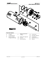
Due to the weight (approx. 70 lbs) of the HP cylinder jug,
adequate support should be provided to prevent damage to
the plunger or seals during disassembly/ re-assembly. See
Figure 7.2 for suggested special tools to support the HP
cylinder jug for this procedure.
HP Cylinder Jug Removal
1.
Prior to removing electrical power from the pump, extend plunger on end
to be serviced. Remove connector from proximity switch on end of
hydraulic cylinder closest to HP cylinder jug to be removed. Start the
pump in LOW pressure mode, allow approximately 20 seconds for
appropriate startup and cycling of intensifier to extend and stop toward
the disconnected proximity switch. Shut off the pump, shut off LP water
supply, observe LOCK-OUT/ TAG-OUT safety rules.
Before performing maintenance on the waterjet pump
observe electrical LOCK OUT/TAG OUT procedures.
2.
Disconnect HP and LP piping / hoses per paragraph 7.2.1 above.
3.
With support cradle tool located under HP cylinder jug, unthread and
remove jug from plunger and hydraulic cylinder head.
NOTE:
several methods for rotating the HP cylinder jug are available. The
cylinder wrench is available, or the jug can be rotated by hand with the help of
the studs and stud nuts. A slight lift force applied to the HP gland nut of the
outlet HP check valve can help ease the effort of rotating the HP cylinder jug.
HP Cylinder Jug Re-Installation
1.
Verify that HP cylinder threads are adequately lubed with High Purity
Goop and that the threads have been sanded/ dressed if galling was
encountered during HP cylinder jug removal.
2.
Verify that the HP plunger seals, packing follower, and plastic cylinder
liner tube are correctly installed. Align HP cylinder jug with plunger
using cradle tool to support weight and provide approximate alignment.
Carefully push/ lift jug into place until threads are ready to engage.
Summary of Contents for STREAMLINE SL-IV PLUS
Page 44: ...SECTION 6 LOW PRESSURE WATER May 2003 6 4 05148390 Figure 6 2 LP Cutting Water Supply Circuit ...
Page 78: ...SECTION 7 HIGH PRESSURE WATER May 2003 p 7 30 49831951 ...
Page 82: ...SECTION 8 ELECTRICAL SYSTEM Aug 2002 p 8 4 49836323 ...
Page 111: ...SECTION 12 PARTS LISTS July 2003 page 12 5 49836349 ...
Page 113: ...SECTION 12 PARTS LISTS July 2003 page 12 7 49836349 ...
Page 115: ...SECTION 12 PARTS LISTS July 2003 page 12 9 49836349 ...
Page 117: ...SECTION 12 PARTS LISTS July 2003 page 12 11 49836349 ...
Page 119: ...SECTION 12 PARTS LISTS July 2003 page 12 13 49836349 ...
Page 121: ...SECTION 12 PARTS LISTS July 2003 page 12 15 49836349 ...
Page 123: ...SECTION 12 PARTS LISTS July 2003 page 12 17 49836349 ...
Page 125: ...SECTION 12 PARTS LISTS July 2003 page 12 19 49836349 ...
Page 127: ...SECTION 12 PARTS LISTS July 2003 page 12 21 49836349 ...
Page 129: ...SECTION 12 PARTS LISTS July 2003 page 12 23 49836349 ...
Page 131: ...SECTION 12 PARTS LISTS July 2003 page 12 25 49836349 ...
Page 133: ...SECTION 12 PARTS LISTS July 2003 page 12 27 49836349 ...
Page 135: ...SECTION 12 PARTS LISTS July 2003 page 12 29 49836349 ...
Page 137: ...SECTION 12 PARTS LISTS July 2003 page 12 31 49836349 ...
Page 139: ...SECTION 12 PARTS LISTS July 2003 page 12 33 49836349 ...
Page 141: ...SECTION 12 PARTS LISTS July 2003 page 12 35 49836349 ...
Page 143: ...SECTION 12 PARTS LISTS July 2003 page 12 37 49836349 ...
Page 145: ...SECTION 12 PARTS LISTS July 2003 page 12 39 49836349 ...
Page 146: ......
Page 147: ......


