Section 2
Installation
20428689
10-2007/Rev 04
2-11
NOTE
Before interrupting the cut, back the cutter blade away from the tubing. Use
compressed air or a small brush to remove the accumulation of chips from the
blades and the tubing throughout the coning operation.
8.
Continue the operation until the feed nut bottoms on the housing. Turn the cutter handle
several more rotations to face-off the end of the cone.
9.
Retract the cutter blade, loosen the gland nut and remove the tubing. Inspect the cone for
surface finish and completeness.
NOTE
Clean the machining chips from the blade and from the collet before coning the
next tube.
Power Coning
1.
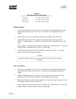
Secure the tubing in a tube vise. No more than the recommended length of tubing should
extend beyond the face of the vice. See Table 2-8, Recommended Extension Length.
2.
Mount the coning tool in a 3/8-inch or 1/2-inch, variable speed power drill. Apply cutting
oil to the end of the tube and slide the coning tool on the tubing.
3.
Apply steady pressure against the end of the tubing while the cone is being cut.
Apply cutting oil frequently and liberally throughout the cutting operation. A medium
weight cutting oil with high sulfur content is recommended.
4.
The tool will stop cutting when the tube angle and facing is complete.
NOTE
Clean the machining chips from the blade and body of the tool before coning the
next tube.
Summary of Contents for STREAMLINE SL-V SRP 100
Page 23: ......
Page 25: ......
Page 174: ...Section 12 Parts List 20428786 2 2008 Rev 05 12 5 Figure 12 1 SL V SRP 100 Intensifier Unit ...
Page 176: ...Section 12 Parts List 20428786 2 2008 Rev 05 12 7 Figure 12 2 Intensifier Assembly ...
Page 184: ...Section 12 Parts List 20428786 2 2008 Rev 05 12 15 Figure 12 7 High Pressure Piping ...
Page 188: ...Section 12 Parts List 20428786 2 2008 Rev 05 12 19 Figure 12 9 Hydraulic Power Package ...
Page 190: ...Section 12 Parts List 20428786 2 2008 Rev 05 12 21 Figure 12 10 Motor Pump Assembly ...
Page 192: ...Section 12 Parts List 20428786 2 2008 Rev 05 12 23 Figure 12 11 Hydraulic Manifold Assembly ...
Page 194: ...Section 12 Parts List 20428786 2 2008 Rev 05 12 25 Figure 12 12 Hydraulic Hose Connections ...
Page 196: ...Section 12 Parts List 20428786 2 2008 Rev 05 12 27 Figure 12 13 Reservoir Assembly ...
Page 199: ...Section 12 Parts List 20428786 2 2008 Rev 05 12 30 Figure 12 14 Bulkhead Pipe Assembly ...
Page 201: ...Section 12 Parts List 20428786 2 2008 Rev 05 12 32 Figure 12 15 Cover Assembly ...
Page 205: ...Section 12 Parts List 20428786 2 2008 Rev 05 12 36 Figure 12 17 Electrical Assembly 230 50 60 ...
Page 223: ...Section 12 Parts List 20428786 2 2008 Rev 05 12 54 Figure 12 25 High Pressure Transducer ...
Page 224: ......
Page 225: ......
Page 226: ......
Page 227: ......
Page 228: ......
Page 229: ......
Page 230: ......
Page 231: ......
Page 232: ......
Page 233: ......
Page 234: ......
Page 235: ......
Page 236: ......
Page 237: ......
Page 238: ......
Page 239: ......


