Section 8
Electrical System
20428746
2-2006/Rev 01
8-2
8.3
Operation
Electrical power from the utility grid enters the main circuit breaker/disconnect on the electrical
enclosure door as 3-phase alternating current. The power is then distributed in two directions.
The 3-phase AC, at the voltage provided from the grid, is routed to the motor starter contactors
and then to the main motor. Single phase AC is routed to the transformer.
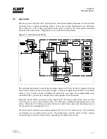
Figure 8-1: Electrical Control Power
The multi-tap transformer converts the incoming voltage to 230 volt AC that is routed to both the
motor starter contactors and to the power supply. The power supply then provides 24 volt direct
current to the control circuits, including the emergency stop logic, the programmable logic
controller (PLC), optical relays, display screen and optional control functions.
When the
START
button is pressed on the control panel, the motor control relay closes and 230
volt AC power is sent to the contactor coils. The coils close, sending the incoming power to the
motor. When the
STOP
button is pressed, the motor control relay opens, disconnecting power to
the contactor coils, stopping the motor.
The motor starter contactors are solenoid operated by 230 volt AC control power. The contactors
are arranged in a wye-delta starter circuit. Wye-delta starter circuits consist of three, 3-phase
contactors used to start the motor slowly, minimizing the initial current draw.
8
007
918
9_1
Summary of Contents for STREAMLINE SL-V SRP 100
Page 23: ......
Page 25: ......
Page 174: ...Section 12 Parts List 20428786 2 2008 Rev 05 12 5 Figure 12 1 SL V SRP 100 Intensifier Unit ...
Page 176: ...Section 12 Parts List 20428786 2 2008 Rev 05 12 7 Figure 12 2 Intensifier Assembly ...
Page 184: ...Section 12 Parts List 20428786 2 2008 Rev 05 12 15 Figure 12 7 High Pressure Piping ...
Page 188: ...Section 12 Parts List 20428786 2 2008 Rev 05 12 19 Figure 12 9 Hydraulic Power Package ...
Page 190: ...Section 12 Parts List 20428786 2 2008 Rev 05 12 21 Figure 12 10 Motor Pump Assembly ...
Page 192: ...Section 12 Parts List 20428786 2 2008 Rev 05 12 23 Figure 12 11 Hydraulic Manifold Assembly ...
Page 194: ...Section 12 Parts List 20428786 2 2008 Rev 05 12 25 Figure 12 12 Hydraulic Hose Connections ...
Page 196: ...Section 12 Parts List 20428786 2 2008 Rev 05 12 27 Figure 12 13 Reservoir Assembly ...
Page 199: ...Section 12 Parts List 20428786 2 2008 Rev 05 12 30 Figure 12 14 Bulkhead Pipe Assembly ...
Page 201: ...Section 12 Parts List 20428786 2 2008 Rev 05 12 32 Figure 12 15 Cover Assembly ...
Page 205: ...Section 12 Parts List 20428786 2 2008 Rev 05 12 36 Figure 12 17 Electrical Assembly 230 50 60 ...
Page 223: ...Section 12 Parts List 20428786 2 2008 Rev 05 12 54 Figure 12 25 High Pressure Transducer ...
Page 224: ......
Page 225: ......
Page 226: ......
Page 227: ......
Page 228: ......
Page 229: ......
Page 230: ......
Page 231: ......
Page 232: ......
Page 233: ......
Page 234: ......
Page 235: ......
Page 236: ......
Page 237: ......
Page 238: ......
Page 239: ......


