background image

Version 2012-10 

Technical Data are subject to change without notice! 

16 


Diameter (mm) 


Windings 


Fine adjustment capacitor 

parallel to coil 

We recommend a capacitor decade e.g  


100pF .... 11,111 µF 


1000 

4-5 

100-200nF (Type MKT or MKS 250V) 

490 

4-5 

100-200nF (Type MKT or MKS 250V) 

290 

100-200nF (Type MKT or MKS 250V) 

190 

--- 

150 

--- 

120 

10 

--- 

80 

12 

--- 

45 

16 

--- 

20 

25 

--- 


0

200

400

600

800

1000

1200

0

5

10

15

20

25

30

D

ia

m

e

te

m

m

Windings

Optimum windings for steel shafts

Magnetic field 

100-200nF 

Summary of Contents for TEL1-PCM-HS-BATT

Page 1: ...ng g S Sh ha af ft ts s Gain and Auto Zero setting direct from Receiver Side Easy to assemble and operate ICP current 4mA Gain selectable to 2 4 8 16 For strain gages or IPC sensors Digital transmission realized inductively Strain gage sensors 350 Ohm Distance up to 50mm Full and half bridge configuration No influence through radio frequency Excitation fixed 4 Volt DC Many systems can operated at ...

Page 2: ...s the actual level and a successful Auto Zero calibration Overload is indicated by the last LED s in pos or neg direction of the bar graph These OVL LED s operate in peak hold mode and are reset by pressing the overload switch Strain gage sensors 350 Ohm in full and half bridge configuration can be directly connected to the transmitter The excitation is fixed to 4 Volt DC and the gain is set by th...

Page 3: ... Sampling rate 104 kHz Operating temperature 10 to 80 C Dimensions 62 x 27 x 13mm without connectors Weight each module 30 grams Static acceleration up to 3000g Powering Battery 6 9V Power consumption 70mA at 6V Optional additional inductive powering TEL1 PCM HS BATT ICP For all ICP sensors Curren 4mA fixed Gain 1 2 4 8 16 32 selectable from receiver side Gain Resolution 250 1 at ICP 12 bit 500 2 ...

Page 4: ...stance to far Power ON LED Red ON if power switch on Rear side Output to Powerhead via 5pol Tuchel Fuse LED Flashing if fuse is defect Powering 10 30V DC Input via 7pol Tuchel Switch ON OFF Operating temperature 10 to 70 C Dimensions 200 x 105 x 44 without connectors Weight 950 grams Static acceleration up to 200g System accuracy without sensor 0 2 TEL1 PCM HS Pickup Function Receiving inductive m...

Page 5: ...Version 2012 10 Technical Data are subject to change without notice 5 Transmitting Part Strain gage connection The pins for battery 6 9V and GND Coil connection Inductive coil Battery ...

Page 6: ...Version 2012 10 Technical Data are subject to change without notice 6 Block diagram Note The Powerhead must be fixed in the middle of the coil in a distance from 5 up to 50 mm ...

Page 7: ...t 10V Negative Bargraph LED With overload indicator Power On LED LED ON Error data transmission LED Flashing Battery voltage lower 6V Reset button of overload indicator AZ button Gain switch Power In DC 10 30V Data input from Pickup head Power ON OFF switch PCM OUT for Interface Option Flashing if fuse damage Positive Baragraph LED With overload indicator ...

Page 8: ...Version 2012 10 Technical Data are subject to change without notice 8 Pin connection cable Pickup Distance of 5 100mm DC Power cable ...

Page 9: ... 5 6 Mount 2 layers of the special ferrite tape around the shaft each layer seperatly without overlap Coil depends of shaft diameter 4 25 parallel windings of 0 5 CUL wires see table for help Fix with 2 layers of mounting tape around the shaft Fix with 3 4 layers of mounting tape around the shaft ...

Page 10: ...ction of the units in the idle state of the shaft During the rotation test appropriate safety precautions should be taken The entire installation may be used only by authorized persons By using tape for the attachment it has to be used in the direction of rotation of the shaft and the end has to be secured Only non elastic tapes with high tensile strength should be used for pre fixing Additionally...

Page 11: ...ound the shaft The table standing below will help you to find the right number windings for steel shafts The table below is a help to estimate the number of windings fast To optimize your results you can try one winding more or less Windings Diameter mm 8 600 8 500 9 250 10 125 11 80 12 40 13 20 Optimum windings for steel shafts 0 100 200 300 400 500 600 0 2 4 6 8 10 12 14 windings diameter Coil d...

Page 12: ...nforderungen der Normen und Richtlinien fulfills the requirements of the standard and regulations of the Directive satisfait aux exigences des normes et directives 108 2004 EG Elektromagnetische Verträglichkeit EMV EMC DIN EN 61000 6 3 Ausgabe 2002 8 Elektromagnetische Verträglichkeit EMV Teil 6 3 Fachgrundnorm Störaussendung DIN EN 61000 6 1 Ausgabe 2002 8 Elektromagnetische Verträglichkeit EMV T...

Page 13: ...erbering 9 D 83624 Otterfing Germany 08024 48737 Fax 08024 5532 Home Page http www kmt gmbh com Email info kmt gmbh com I In nd du uc ct ti iv ve e p po ow we er r s su up pp pl ly y A As ss se em mb bl li in ng g i in ns st tr ru uc ct ti io on ns s f fo or r T TE EL L1 1 P PC CM M H HS S B BA AT TT T ...

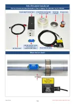
Page 14: ...et Picture shows standard Inductive Power Supply for diameter up to 300mm Mounted on shaft 25 and 50mm mounting tape to fix coil on shaft Power supply for power head DC Power cable IND PWR AC DC module Input AC from coil Output 6 5VDC 100mA CU wire 0 5mm Ferrite tape 30mmx3m Power Head with cable ...

Page 15: ... load of the IND PWR AC DC module and the capacitor in the Power Head must be in resonance to get the optimal transmission The inductive load of the shaft depends of diameters material and number of windings To find the optimal transmission try one winding more ore less The LED on the Inductive Power module will help to find the best configuration The distance between powerhead and the coil is 3 1...

Page 16: ...il We recommend a capacitor decade e g 100pF 11 111 µF 1000 4 5 100 200nF Type MKT or MKS 250V 490 4 5 100 200nF Type MKT or MKS 250V 290 5 100 200nF Type MKT or MKS 250V 190 7 150 9 120 10 80 12 45 16 20 25 0 200 400 600 800 1000 1200 0 5 10 15 20 25 30 Diameter mm Windings Optimum windings for steel shafts Magnetic field 100 200nF ...

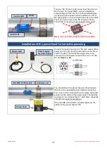
Page 17: ...ering Connect the power head on the AC Out socket of the power box and then the DC power cable on the DC In 10 30V socket The two banana plugs have to be connected to a DC power source with red on 10 30V DC and black on 0V You should mount the power head at a fixed location that it s as free as possible from vibration influences The center of the coil should be in the same horizontal position as t...

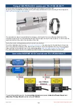
Page 18: ... order to test the electrical function of the units in the idle state of the shaft During the rotation test appropriate safety tools are to be attached The entire installation may be used only by authorized persons By using tape for the attachment it has to be used in the direction of rotation of the shaft and the end has to be secured against removing Only non elastic tapes with high tensile stre...

Page 19: ...inductive power head Example of mounting plate Magnetic field Shaft with Cu wire Coil Don t use for mounting any kind metal in this area 25 30mm Otherwise flow magnetic energy in the metal also and degrease the distance between power head and coil on shaft 25 30mm Wrong Mounting plate cover the active area of inductive head ...

Page 20: ...Version 2012 10 Technical Data are subject to change without notice 20 Dimensions Powerhead 66 Cable length 5m Optional 10 20m 30 Drill d 4 3mm 10 43 53 33 33mm 66 ...

Page 21: ...magnetic sensitive parts devices and systems Do not place the power head in the switched on state on metallic objects because this results in eddy currents which could overload the device and strongly heat up small objects In addition the probe could be destroyed No metallic objects other than the disc type coil should be located in the air gap of the power head The same applies to metallic parts ...

Reviews: