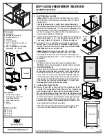
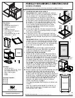
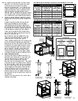
Parts Included
A. Waste Bin(s)
B. Sliding Base Assembly (1)
C. Waste Bin Chassis (1)
D. Template
E. Lid(s) (if supplied)
F. #8x1/2" Mounting Screws for Door
(8 = 4 + 4 extra)
G. #8X1" Mounting Screws for Sliding
Assembly (8 = 6 + 2 extra)
Tools Required
• Phillips head screwdriver
• Drill with 1/16" (1.5mm) bit
for drilling pilot holes
• Tape measure or ruler
• Pencil
• Scissors
Product Assemblies
USC12-1-35
USC12-1-50
USC15-2-35
USC18-2-50
SOFT-CLOSE UNDERMOUNT WASTE BIN
Installation Instructions
Inspect all parts and read all instructions prior to beginning assembly and installation.
310188-E-0814
2700 Oak Industrial Drive NE , Grand Rapids, MI 49505 USA
800.253.1561 • 616.459.3311 • www.kv.com
©2014 Knape & Vogt. All rights reserved. Made in USA.
Knape & Vogt
®
reserves the right to change specifications without notice.
4A
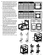
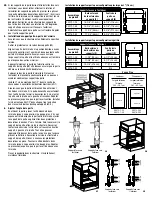
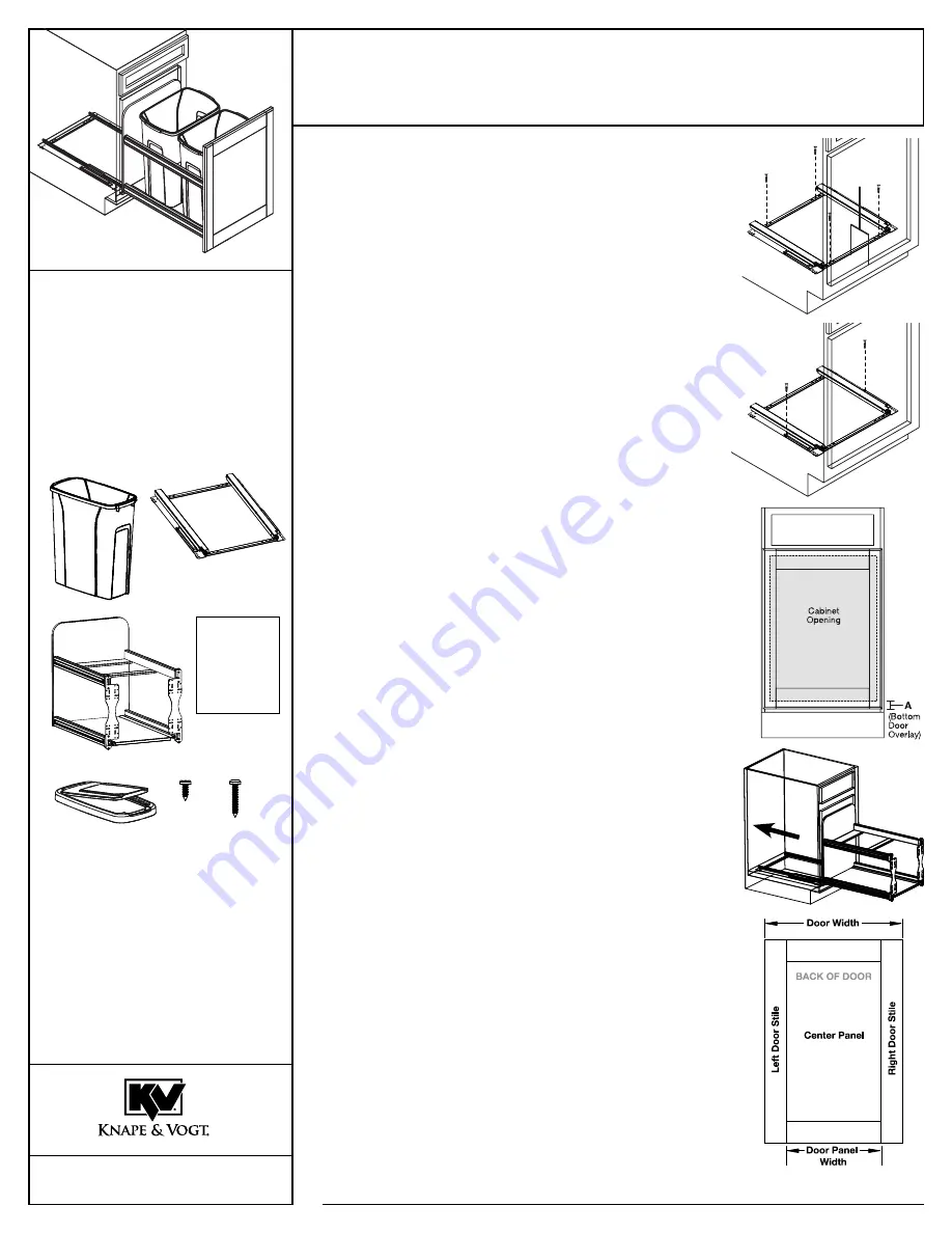
1. Install Sliding Base Assembly
Optional Step:
Place slide assembly installation template on cabinet
floor. Drill 6 holes at locations shown on template with 1/16" drill bit.
Skip to step 1A.
Place sliding base assembly on cabinet floor. Align centering mark on
front mounting strap with the center of the cabinet opening. Position front
edge of the front mounting strap 1-1/4" back from the outside edge of the
front of the cabinet. For a fully inset door application, measure 1-1/4"
back from inside edge of the cabinet face frame. Completely close door
to make sure the assembly will not interfere.
1A.
Once the position is determined, fasten the sliding base assembly to the
cabinet floor by using 4 – #8 x 1" mounting screws through the interior
holes shown in figure 1A. Tighten with a Phillips head screwdriver.
1B.
Next, place 2 – #8 x 1" mounting screws through the exterior holes
shown in figure 1B and fasten with a Phillips head screwdriver until
the head of the screw is flush with the sliding base assembly.
DO NOT
OvER TIghTEN
as this can warp the slide.
Optional Step:
Mark mounting hole positions with a pencil then
remove sliding base assembly and drill pilot holes. Place sliding
assembly back into position and fasten with #8x1" mounting screws.
For additional stability, fasten extra 4 – #8x1" mounting screws through
outside holes.
2. Remove Door
With drill or screwdriver, remove door hinges from cabinet and door.
IMPORTANT: Door must be removed prior to Waste Bin Chassis installation.
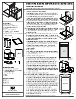
3. Install Waste Bin Chassis
Lower and insert rear of chassis so that the channels on the chassis fit
onto the slides on the sliding base assembly. Push chassis toward the
back of the cabinet until it sits against the back of the slides and you
hear a "click". The chassis is now fully seated and locked. Grasp the
door mount brackets, slowly pull the chassis out of the cabinet until it
stops moving. Both slides should fully extend. NOTE: If your slides do
not fully extend, your chassis is not seated properly. To correct, push
the drawer slide forward until it locks into position.
4. Determine Door Bracket Position
4A.
Measure the door width by measuring from the outside edge of the left
door stile to the outside edge of the right door stile. Then, determine the
center door panel width by measuring from the inside edge of the left
door stile to the inside edge of the right door stile. These two measurements
determine the door bracket mounting area. Locate your product assembly
on the charts that follow. Select the Outside to Outside Edge of Brackets
(Z) measurement that fits within your door bracket mounting area. This
determines if your Brackets Face Outward or Inward, as shown on chart.
If your door brackets face inward, go to step 5.
NOTE: All USC18-2-50 unit door brackets face outward. USC18-2-50
unit is pre-assembled with door brackets outward. Skip to Step 5.
A
E
F
B
C
D
g
2
3
1B
1-1/4"
(3.2 cm)
1A
DO NOT
OvER
TIghTEN
Template