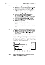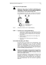
Maintenance by the user
19
SOP 9
Assembling the pump head
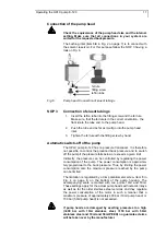
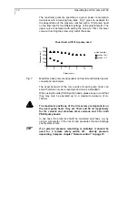
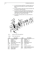
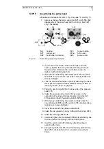
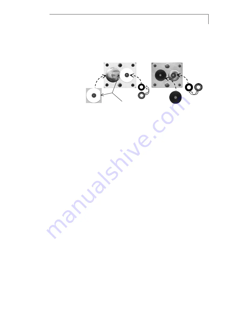
All positions of components refer to Fig. 9 on page 18. and Fig. 10.
1. Always exchange the piston seals item
3.11
and
3.11a
after
disassembly of the pump head and the O-rings, item
3.21
only if nescessary.
3.4
3.20
3.13
3.12
plane areas
180°
180°
3.11
3.11a
3.4
housing
3.13
pressure plate
3.11
piston seal
3.11a
piston seal
3.12
seal holder (ceramics)
3.20
pressure disc
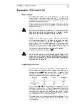
Fig. 10
Parts of the opened pump head
2. If you have removed the ceramic seal holder out of the
housing, replace them very carefully with the plane sides
faced together. Otherwise the seal holders cannot be
replaced without damaging them.
3. With the open side facing downwards press the new piston
seals
3.11
into the ceramic seal holder carefully. Make sure
to keep it straight.
4. Lock the ceramic seal holder in place by attaching the check
valves
3.10
and distance holder
3.10a
according to SOP 12
“
Cleaning check valves“
on page 20.
5. Place the new O-rings
3.21
in the inner side of the pressure
plate
3.13
.
6. Install the pressure plate, item
3.13
. Take care on the
orientation of housing and pressure plate. Using the SW
5/16 spanner, tighten the spacing bolts,
3.14
firmly.
7. With the open side facing downwards carefully press the
new piston seals
3.11a
into the spaces of the pressure plate,
making sure to keep it straight.
8. Cover the seals with the pressure discs
3.20
.
9. Install the two guides for spring,
3.16
and the springs,
3.15
.
10. Install the retaining plate,
3.18
.
11. Insert and tighten the two screws
3.19
strictly alternating due
to strong force of the springs,
3.15
behind the plate.
12. Insert the piston rods
3.17
carefully without bending or
quenching the rods.
13. The spacing bolts, item
3.14
and the retaining plate screws,
item
3.19
must be tightened to be seated as securely as
before.


