Diaphragm pump N87.9 EX
Servicing
Translation of Original Operation and Installation Instruction, english, KNF 323252 04/21
29
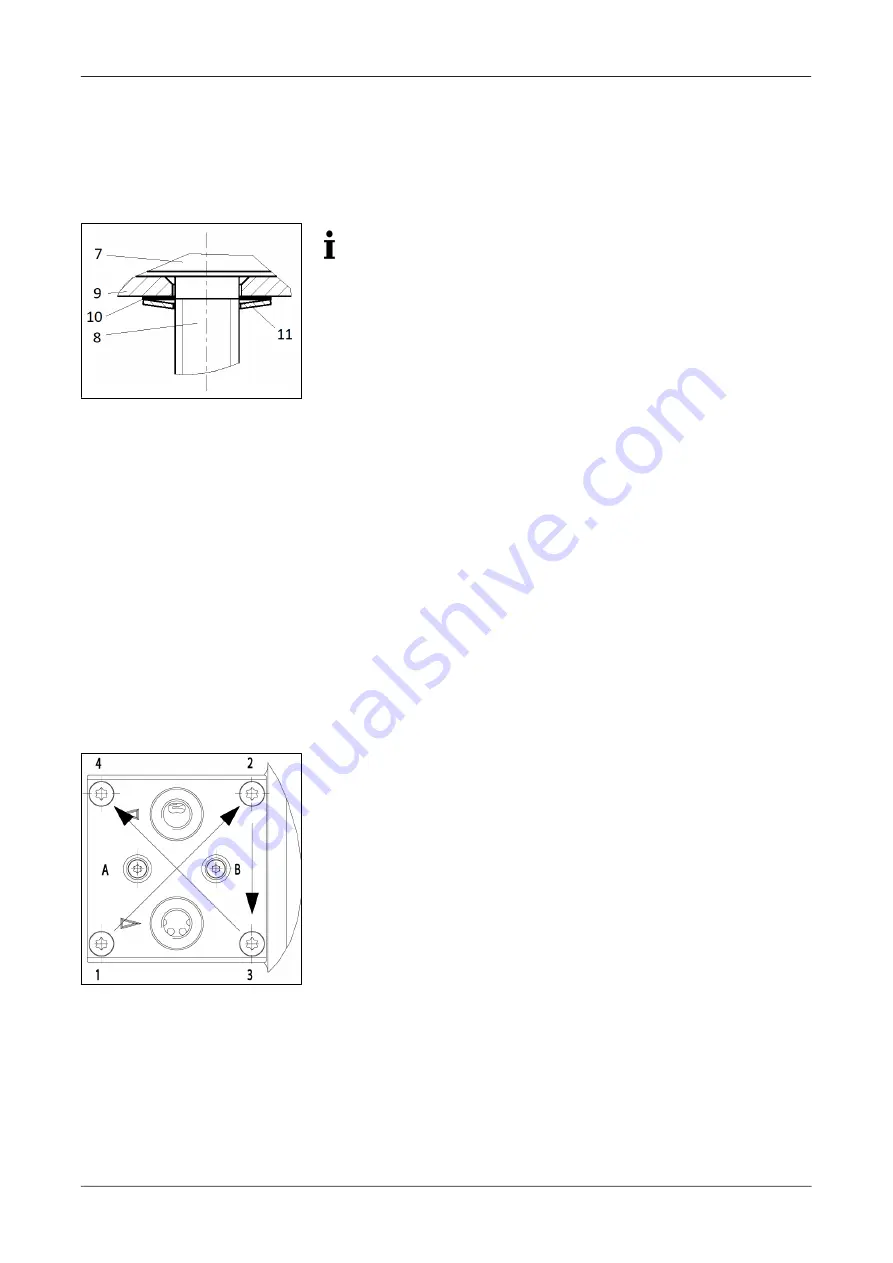
4. Remove the diaphragm support (9), shim ring(s) (10) and disc spring
(11) from the threaded bolt (8) of the structured diaphragm and keep in
a safe place.
5. Check all parts for soiling and clean them if necessary.
6. Push diaphragm support (9), shim ring(s) (10) and disc spring (11)
onto the threaded bolt (8) of the new structured diaphragm (7) in this
order (see Fig. 5).
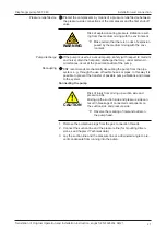
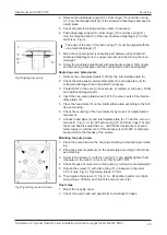
Fig.5 Aligning disc spring
The edge of the disc of the disc spring (11) must be aligned with the
structured diaphragm (7).
7. Move the connecting rod (connection part between drive shaft and
structured diaphragm) to the upper reversal point by turning the coun-
terweight.
8. Screw the structured diaphragm with diaphragm support, shim ring(s)
and disc spring clockwise onto the connecting rod and hand tighten.
Replacing valve plates/seals
1. Remove the valve plates/seals (12) from the intermediate plate (6).
2. Check the valve seats, intermediate plate (6) and head plate (5) for
soiling and damage. Clean the parts if necessary.
3. Contact KNF in the event of unevenness, scratches or corrosion. Order
and replace damaged parts.
4. Insert the new valve plates/seals (12) in the valve seats of the interme-
diate plates (6).
5. Place the head plate (5) on the intermediate plate according to the felt-
tip pen marking.
6. Check the centering of the head plate (5) by means of a slight lateral
movement.
7. Connect head plate (5) and intermediate plate (6). To do this, screw in
screws (3; Fig. 6: A + B) with disc spring (11) and shim rings (10) until
the screw head is seated flat, i.e., until the first resistance is encoun-
tered. Apply a small amount of thread locker (Loctite 222 or compara-
ble product) to the threads of the screws.
Mounting the pump head
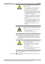
Fig.6 Tightening cap head screws
1. Place the pump head on the housing according to the felt-tip pen mark-
ing.
2. Place the pressure plate (4) on the head plate according to the felt-tip
pen marking.
3. Screw in the screws (1) with disc spring (11) and slightly tighten them
crosswise in the order 1-2-3-4 (see Fig. 6) with 1 Nm.
4. Check for ease of movement of the pump by turning the counterweight.
5. Tighten the screws (1) with disc spring (11) crosswise in the order
1-2-3-4 (see Fig. 6). Tightening torque: 2.1 Nm.
6. Then tighten the screws (3; Fig. 6: A + B) another quarter turn (tight-
ening torque: 30 Ncm) and mount the screw covers (2).
Final steps
1. Mount the housing cover.
2. Check the pump head and pneumatic connections for leaks.

