8
insulation resistance at a winding temperature of 25 °C is smaller than 30 MΩ, or smaller than 1 MΩ at
a winding temperature of 75 °C, the motor winding should be dried until the required minimum
insulation resistance is reached. The winding temperature should not exceed 80 °C in this regard!
Loosen the bearing plate, so that an air exchange can be carried out with closed motors. After the
winding has been dried out, the bearing needs to be serviced (see corresponding chapter!).
3.6 Electrical connection
The mains voltage and frequency must match the data on the rating plate. Voltage differences of ±5%
and/or frequency differences of ±2% are permissible as described in sector A in accordance with EN
60034-1. We ask that you note this when connecting the motors.
A connection diagram is enclosed with each motor upon delivery. Connection of the motor and the
control system,as well as overload protection and earthing, must be done in accordance with the VDE
and installation instructions and the EVU provisions.
The direction of rotation of the shaft end on the output side must be checked before commissioning.
Reversal of the direction of rotation is possible by swapping any two voltage phases.
The insertion parts intended for tension relief or as anti-rotation protection for the supply lines must be
used properly. Seal any openings which are not required.
Tightening torques for terminal board connection screw connections (see page 11)
3.7 Motor protection
3.7.1 Thermistor
Connect the built-in thermistor to the tripping device in accordance with the connection diagram in the
terminal box cover or provided with the motor. Only carry out any continuity tests which may be
required with a measuring bridge (max. 2.5 V).
3.8 Commissioning
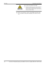
Caution
The surface of the drive may reach high temperatures during operation.
Danger of burns
► Secure hot surfaces against operation or unintentional contact. To this
end, attach covers or warning according to the regulations.
► Allow the motor to cool sufficiently before commencing any work.
Installation of the transmission elements
Only use appropriate tools and devices for fitting and removing the transmission elements. No
pressure or impacts may be transmitted to the motor bearings.
Alignment during coupling operation
During coupling operation, the shafts must be axially and radially aligned against each other.
Adjustment of the air between the coupling halves must be done in accordance with the coupling
manufacturer's specifications.
Use only couplings which are flexible in terms of centre offset, angle, length and torsion. Rigid
couplings are not permitted and may only be used in exceptional cases after consultation with the
manufacturer.
Before commissioning, the following at a minimum must be checked:
•
The runners can be turned without scraping,
•
The motor is properly aligned and installed,
•
The drive elements have the correct settings,
•
All electrical connections, connection elements and mounting screws are properly tightened and
implemented,
Summary of Contents for N630.12
Page 65: ...13...
Page 67: ...15 9 Documents provided Circuit diagram...
Page 69: ......
Page 82: ...13...
Page 84: ...15 9 Documents provided Circuit diagram...
Page 87: ......
Page 88: ...KNF worldwide You can find our local KNF partners at www knf com...

