12
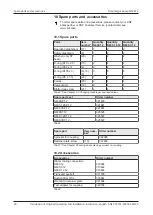
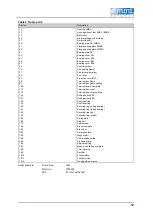
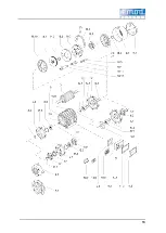
Table 3: Spare parts
Part no.
Description
1.0
1.1
1.2
2.0
3.1
4.0.
4.1
4.2
5.1
6.0
6.1
6.2
6.3
6.4
7.0
7.1
8.2
8.3
9.2
9.3
10.0
11.2
11.3
12.0
12.1
13.0
13.1
14.0
14.1
14.2
14.3
15.0
16.0
17.1
18.0
18.1
18.2
18.3
18.4
18.5
18.6
18.7
18.8
18.9
18.10
18.11
18.12
Housing (IMB3)
Housing without feet (IMB5 / IMB14)
Motor feet
Stator package with winding
Rotor with shaft
Bearing plate AS (IMB3)
Flange bearing plate (IMB5)
Flange bearing plate (IMB14)
Bearing plate BS
Bearing cover ASi
Bearing cover ASa
Bearing cover BSi
Bearing cover BSa
Centrifugal disc
Fan (thermoplastic)
Fan (aluminium alloy)
Fan cover
Protective roof (IMV1)
Terminal box frame
Terminal box frame sealing
Terminal board, complete
Terminal box cover
Terminal box cover sealing
Rolling bearing AS
Rolling bearing BS
Shaft seal ring
Shaft seal ring
Securing ring (rolling bearing)
Securing ring (rolling bearing)
Securing ring (fan)
Securing ring (brake)
Spring plate
Ring bolt
Cable screw
Brake, complete
Brake disc
Armature plate
Magnet part
Compression spring
Pressure piece
Adjustment ring
Manual ventilation, complete
Terminal strip
Rectifier
Friction plate
Cylinder screw
Re-adjustment sleeve
Order example:
Frame size:
Motor no.:
Part:
160L
3574507
3.1 rotor with shaft
Summary of Contents for N630.12
Page 65: ...13...
Page 67: ...15 9 Documents provided Circuit diagram...
Page 69: ......
Page 82: ...13...
Page 84: ...15 9 Documents provided Circuit diagram...
Page 87: ......
Page 88: ...KNF worldwide You can find our local KNF partners at www knf com...

