7
Motors with cylindrical roller bearings are protected against bearing damage by transport protection.
The transport protection must be removed before raising of the transfer elements and commissioning.
2.2 Storage
The storage location should be as dry, clean, stable in temperature and free from vibrations as
possible.
So that the lubrication film in the motor bearings and the sealing systems is not stripped off, the motor
shaft should be turned a few times by hand, e.g. at monthly intervals, during long storage periods.
The motor rolling bearings should be re-greased or replaced if the period between delivery and
commissioning is more than 4 years. In unfavourable storage conditions, this period is significantly
reduced.
3
Installation and commissioning
Danger
Installations and work may only be carried out with the device
deenergised (separated from the mains) and the motor shut down.
Death, cardiac arrhythmia
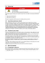
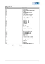
► Observe the 5 safety rules, see chapter List of safety and installation notes
on page 5
3.1 Positioning
3.1.1 Location
The motors should be installed/fitted while easily accessible and at an ambient or coolant temperature
of max. +50°C. Higher coolant or ambient temperatures of up to 60 °C, with corresponding power
reduction, are possible after consultation with the manufacturer.
The cooling air should be able to flow in and out unhinderedly and should not be directly sucked in
again. The air inlets and outlets, as well as the channels between the cooling ribs, should be protected
against dust and dirt and regularly cleaned.
If the product is installed with the shaft end upwards or downwards, it should be guaranteed that no
water can penetrate the upper bearing.
3.2 Mountings for motors
Foot-mounting motors must be positioned and mounted on an even, vibration-free surface. All
mounting feet must lie flat; place thin sheets underneath for levelling if necessary.
For flange motors, care must be taken to ensure the axial run-out of the counterflange. Axial run-out
errors may result in bearing damage and/or the failure of sealing systems.
3.3 Condensation drain holes
Care must be taken to ensure that the available condensation drain holes are located at the lowest
point of the motor after installation and are kept free from dirt.
Closed condensation drain holes (if present) should be opened from time to time and closed again
before each start-up.
Summary of Contents for N630.12
Page 65: ...13...
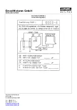
Page 67: ...15 9 Documents provided Circuit diagram...
Page 69: ......
Page 82: ...13...
Page 84: ...15 9 Documents provided Circuit diagram...
Page 87: ......
Page 88: ...KNF worldwide You can find our local KNF partners at www knf com...

