background image

Servicing 

Diaphragm Vacuum Pumps N 920__.18 and N 920 KT.29.18G 

24 

Translation of original Operating Instructions, English, KNF 121416-121419 07/18 

Mount pump head 

1.   Place head plate (

10

) on intermediate plates (

11

), (

14

) and 

(

15

) in the position indicated by the drawing lines. 


At the front edge the three intermediate plates must lie in a 

line on which head plate is placed flushly. 

2.   Tighten the three screws (

7

) of head plate (

10

) carefully slightly 

hand-tight. 


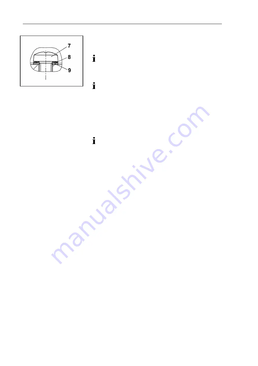
For position and orientation of disk spring (

8

) and washer (

9

of screw (

7

) see fig. 10. 

3.   Place head cover (

4

) on pump housing (

18

). 

4.   Tighten the nine screws (

3

) of head cover (

4

) slightly in the first 

instance. Start with the screws of medium pump stage, then 

tighten the screws on the right, at least these on the left. 

5.   Now, tighten the screws (

3

) firmly; tighten the center screws 

first, then continue outward. 


If the screws are stiff to turn, the intermediate plates do not 
lie in a line at front edge, or intermediate plates and head 

plate are not placed flushly (see step 1). 

6.   Remount the covers (

5

). 

7.   Remount pump handhold (

2

). 


Final steps 

1.   Reconnect suction and pressure line to the pump. 

2.   Reconnect the pump to the electricity supply. 


If you have any questions about servicing, call your KNF technical 

adviser (see last page for contact telephone number). 


Fig. 10: Posit ion and orient at ion 

of  disk (

8

) and washer (

9

) at  

screw (

7

Summary of Contents for N920 AP.18

Page 1: ... 18G KNF Neuberger GmbH Alter Weg 3 D 79112 Freiburg Germany Phone 49 0 7664 5909 0 Fax 49 0 7664 5909 99 E Mail info knf de www knf de Contents Page 1 About this document 3 2 Use 4 3 Safety 5 4 Technical Data 7 5 Design and Function 10 6 Installation and connection 12 7 Operation 13 8 Servicing 16 9 Troubleshooting 25 10 Spare parts and accessories 27 11 Returns 28 12 Health and safety clearance ...

Page 2: ......

Page 3: ...NING A danger warning is located here Possible consequences of a failure to observe the warning are specified here The signal word e g Warning indicates the danger level Measures for avoiding the danger and its conse quences are specified here Danger levels Signal word Meaning Consequences if not observed DANGER warns of immedi ate danger Death or serious injuries and or serious damage are the con...

Page 4: ...lication case Before using a medium check the compatibility of the materials of the pump head diaphragm and valves with the medium Only transfer gases which remain stable under the pressures and temperatures occurring in the pump Laboratory equipment or additional components connected to a pump have to be suitable for use with the pneumatic capabilities of the pump see chapter 4 2 2 Improper use T...

Page 5: ... with notice sticker see fig 1 only after separating mains plug from power source When transferring dangerous media observe the safety regula tions when handling these media Be aware that the pumps are not designed to be explosion proof Make sure the temperature of the medium is always sufficiently below the ignition temperature of the medium to avoid ignition or explosion This also applies for un...

Page 6: ...y and the EC Directive 2006 42 EC concerning Machinery The following harmonized standards have been used DIN EN 61010 1 DIN EN 61326 1 class A DIN EN 50581 The pumps correspond to IEC 664 the overvoltage category II the pollution degree 2 Only have repairs to the pump carried out by the KNF Customer Service responsible Only authorized personnel should open those parts of the housing that contain l...

Page 7: ...S Diaphragm PTFE coated Valve EPDM Gas ballast valve PVDF Tab 3 Refer to the type plate for the pump s electrical configuration The pump is supplied by a universal power supply with inte grated overload protection It is protected against overheating by a temperature sensor on the motor board and equipped with overcurrent protection If one of these safety functions is triggered the pump will be shu...

Page 8: ...media temperature Permissible ambient temperature 10 C to 40 C Permissible media temperature 5 C to 40 C Other parameters Weight kg 10 5 Dimensions L x H x W mm 324 x 226 x 158 Maximum permissible ambient relative humidity 80 for temperatures up to 31 C decreasing linearly to 50 at 40 C Max altitude of site m above sea level 2000 Electrical Data Automatic mains power ad justment 100 240 V 50 60 Hz...

Page 9: ...ent and media temperature Permissible ambient temperature 10 C to 40 C Permissible media temperature 5 C to 40 C Other parameters Weight kg 8 5 Dimensions L x H x W mm 324 x 226 x 158 Maximum permissible ambient relative humidity 80 for temperatures up to 31 C decreasing linearly to 50 at 40 C Max altitude of site m above sea level 2000 Electrical Data Automatic mains power ad justment 100 240 V 5...

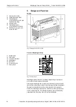
Page 10: ... KT 29 18G Function Diaphragm Pump 1 Outlet valve 2 Inlet valve 3 Transfer chamber 4 Diaphragm 5 Eccentric 6 Connecting rod 7 Pump drive Fig 3 Pump head Diaphragm pumps transfer compress depending on pump ver sion and evacuate gases and vapors The elastic diaphragm 4 is moved up and down by the eccentric 5 and the connecting rod 6 In the downward stroke it aspirates the gas to be transferred via t...

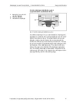
Page 11: ...on diaphragm 3 separates the underside of the working diaphragm from the crank space of the pump see fig 4 The space between the two dia phragms called a vacuum chamber 2 is connected with the suction side of the pump via an balancing connection 1 This way the vacuum chamber has approximately the same pressure as the working space of the diaphragm pump The pressure difference between the upper and...

Page 12: ...Protect the pump from dust Protect the pump from vibration and jolt 6 2 Connection Only connect components to the pump which are designed for the pneumatic data of the pump see chapter 4 If the pump is used as a vacuum pump safely discharge the pump exhaust at the pump s pneumatic outlet A marking on the pump head shows the direction of flow 1 Remove the protective plugs from the pneumatic connect...

Page 13: ...r 2 2 Observe the safety precautions see chapter 3 WARNING Hazard of the pump head bursting due to excessive pressure increase Do not exceed max permissible operating pressure see chapter 4 Monitor pressure during operation If the pressure exceeds the maximum permissi ble operating pressure immediately shut down pump and eliminate fault see chapter 9 Trou bleshooting Only throttle or regulate the ...

Page 14: ...n following a brief power failure If a pump starts against pressure it may block This activates the thermal switch and the pump switches off Make sure that no pressure is present in the lines during switch on Switch on pump with mains switch see fig 2 Depending on the level of the applied electrical voltage initiali zation of the electronics can take up to one second before the pump starts Switchi...

Page 15: ... 7 6 Gas ballast WARNING Personal injury caused by poisoning or explosion and damage to the pump Make sure that no reactive or explosive mixtures will be produced when the gas ballast valve is open When transferring vaporous media opening the gas ballast valve can minimize the formation of condensation in the pump heads Opening the gas ballast valve deteriorates ultimate vacuum performance The gas...

Page 16: ...g or explosion and damage to the pump When flushing the pump with inert gas make sure that the gas ballast valve is closed so no reactive or explosive mixtures can form Before switching off the pump flush it with air if neccesary for safety reasons with an inert gas for about five minutes under atmospheric conditions ambient pressure If inert gas is used Connect the inert gas feed to the gas inlet...

Page 17: ...umatic inlet and outlet Spare part tool Service Set according to chapter 10 Allen key 4 mm Felt tip pen Stabilization diaphragm if required Tab 8 Always replace diaphragm and valve plates together to main tain the pump performance WARNING Health hazard due to dangerous substances in the pump Depending on the substance transferred caustic burns or poisoning are possible Wear protective clothing if ...

Page 18: ...mediate plate head 1 4 Valve plate 5 O ring ø 24 x 2 6 O ring ø 5 5 x 2 7 Intermediate plate head 2 8 Intermediate plate head 3 9 Diaphragm head 1 10 Diaphragm head 2 11 Diaphragm head 3 12 Connecting rod head 2 13 Connecting rod head 3 14 Adapter 15 Pump housing 16 Fan 17 Stabilization diaphragm 18 O ring ø 5 5 x 2 19 Screw Fig 6 Exploded drawing N 920 AP 18 N 920 AP 29 18 ...

Page 19: ...d do not fall into the pump housing If diaphragm spacers should adhere to the diaphragms take them off and put them on the thread of the corresponding connecting rod The same number of diaphragm spacers must be mounted as were used for the previous assembly This is necessary in order to ensure the pump s pneumatic performance 2 Remove the valve plates 4 and O rings 5 from the interme diate plates ...

Page 20: ...inally tighten the diaphragms you are recom mended to move the diaphragm to the upper dead center by rotating the fan 16 13 Screw the new diaphragm 10 and 11 onto the connecting rods 12 and 13 and tighten it by hand Mount valve plates intermediate plates and head cover 1 Lay the new O ring 18 on the adapter 14 2 Lay the new valve plates fig 7 4 and the new O rings 5 on the intermediate plates 3 7 ...

Page 21: ...pare part tool Service Set according to chapter 10 Allen key 4 mm Phillips head screwdriver No 2 Felt tip pen Tab 9 Always replace diaphragm and valve plates together to main tain the pump performance WARNING Health hazard due to dangerous substances in the pump Depending on the substance transferred caustic burns or poisoning are possible Wear protective clothing if necessary e g protective glove...

Page 22: ... plate 12 O ring ø 24 x 2 13 Valve plate 14 Intermediate plate 15 Intermediate plate 16 Diaphragm 17 Adapter 18 Housing 19 Screws 20 Fan 21 Connecting rod 22 Diaphragm 23 Gas ballast valve see fig 10 Fig 8 Exploded drawing N 920 KT 29 18G Remove pump head 1 Undo both screws 1 of pump handhold 2 remove pump handhold see fig 8 2 Undo the nine screws 3 of the head cover 4 3 Undo two screws 6 each and...

Page 23: ...nded to move the diaphragm to the upper dead center by rotating the fan 20 3 Put head plate 10 with intermediate plates 11 14 and 15 on adapter 17 Change valve plates 1 Mark the position of head plate 10 and intermediate plate 11 relative to each other by a drawing line with a felt tip pen This helps avoid incorrect assembly later 2 Mark the position of head plate 10 and intermediate plate 14 rela...

Page 24: ... Tighten the nine screws 3 of head cover 4 slightly in the first instance Start with the screws of medium pump stage then tighten the screws on the right at least these on the left 5 Now tighten the screws 3 firmly tighten the center screws first then continue outward If the screws are stiff to turn the intermediate plates do not lie in a line at front edge or intermediate plates and head plate ar...

Page 25: ...tes are worn Replace diaphragm and valve plates see chapter 8 3 Tab 10 Flow rate pressure or vacuum too low The pump does not achieve the output specified in the Technical data or the data sheet Cause Fault remedy Condensate has collected in pump head Detach the condensate source from the pump Flush pump see chapter 8 2 1 There is gauge pressure on pressure side and at the same time vacuum or a pr...

Page 26: ... on if necessary The pump s overcurrent protec tion circuit has responded Remove the pump from the source of electrical power Determine and eliminate the cause of the overcurrent e g inproper pressure liquid in the pump heads The pump must be unplugged for some seconds before the electronics will allow to restart Tab 12 Pump is switched on but does not run the on off switch on the pump is lit Caus...

Page 27: ...5 Spare parts Order No Service set for N 920 AP 18 057456 Service set for N 920 AP 29 18 057456 Service set for N 920 KT 29 18G 305355 Service set for N 920 KT 29 18 111905 Stabilization diaphragm only for N 920 AP 18 and N 920 AP 29 18 056523 Gas ballast valve 136104 Accessories Order No Silencer Filter G 1 8 007006 Sealing for hose connector 026906 Adjustable delivery through analog signal input...

Page 28: ...ance and decon tamination form For optimal processing of a return a copy of this declaration should be sent in advance via e mail regular mail or fax to KNF Customer Service refer to final page for address In order to avoid endangering employees who open the shipment s packaging despite any residual hazards the original version of the Health and safety clearance and decontamination form must accom...

Page 29: ...Pumps N 920__ 18 and N 920 KT 29 18G Health and safety clearance and decont form Translation of original Operating Instructions English KNF 121416 121419 07 18 29 12 Health and safety clearance and decon tamination form ...

Page 30: ......

Page 31: ......

Page 32: ...KNF worldwide Please find our local KNF partners at www knf com ...

Reviews: