background image

Safety

Diaphragm pump N96_DC-B-M

8

Translation of Original Operating and Installation Instruction, English, KNF 316836-316838 06/22

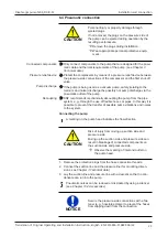
2.3 Working in a safety conscious manner

Observe  the regulations on accident prevention and safety during all work
on the pumps and during operation.

Avoid contact with the pump heads and housing parts because the pump
heats up during operation.

When working on the pump, make sure that the pump is disconnected
from mains and without power.

When connecting the pump to the electrical mains, observe the corre-
sponding safety rules.

Ensure that no hazards arise from gas flowing when gas connections are
open, from the effects of noise or from hot, corrosive, dangerous and envi-
ronmentally hazardous gases.

Make sure that an EMC-compliant installation of the pump is ensured at all
times to prevent the occurrence of dangerous situations.

2.4 Operating conditions

Only use the pump in perfect technical condition, for its intended purpose,
safely and with an awareness of the dangers and in observation of the op-
erating instructions.

Only install and operate the pumps in accordance with the operating pa-
rameters and conditions described in Chapter 

3 Technical data

.

Only pumps that are fully assembled and in the condition as delivered may
be operated.

Make sure that the installation location is dry and that the pump is pro-
tected from rain, splash water, gushing water, dripping water and other
contamination.

Check the tightness of the connections between the pipes of the applica-
tion and the pump (or the connection of the pump) at regular intervals.
Leaky connections carry the risk of releasing dangerous gases and vapors
from the pump system.

2.5 Media

Requirements of pumped media Before transferring a medium, check whether the medium can be trans-

ferred without risk in the specific application.

Take note of any change in the state of matter (condensation, crystalliza-
tion).

Before using a medium, check the compatibility of the media-contacting
components (see 

3 Technical data

) with the medium.

Risk of dangerous gas mixtures during pump operation if diaphragm
breaks: Depending on the medium being transferred, breakage of the di-
aphragm can result in a dangerous mixture if the medium mixes with the
air in the compressor housing or the surroundings.

Only transfer gases that remain stable under the pressures and tempera-
tures that arise in the pump.

Handling of 

hazardous

media

Upon breakage of the diaphragm and/or leaks, the transferred medium
mixes with the air in the surroundings and/or in the pump housing.

Make sure that a dangerous situation cannot arise as a result.

When pumping hazardous media, observe the safety regulations for the
handling of said media.

Handling of combustible media Note that the pump is not designed to be explosion-proof.

Make certain that the temperature of the medium is always sufficiently be-
low the ignition temperature of the medium so as to prevent ignition or ex-
plosion. This also applies for abnormal operating situations.

Summary of Contents for N96ATDC-B-M

Page 1: ...OPERATING AND INSTALLATION INSTRUCTION ENGLISH KNF 316836 316838 06 22 OEM Notice Before operating the pump and accessories read and observe the operating and installation instructions as well as the...

Page 2: ...a 11 Technical data 11 4 Product description and function 14 5 Transport 16 General 16 6 Installation and connection 17 6 1 Installing the pump 17 6 2 Aligning gas connections 19 6 3 Electrical connec...

Page 3: ...hin reach at all times Project pumps For customer specific project pumps pump models that begin with PJ or PM there may be deviations from the operating and installation instruc tions For project pump...

Page 4: ...pecified here Danger levels Signal word Meaning Consequences if not observed DANGER warns of immediate danger Death or serious injury or serious damage will result WARNING warns of possible dan ger De...

Page 5: ...of hot surface Warning of electrical voltage Warning of poisonous substances Warning of hand injuries through crushing ESD protected area Observe the operating instructions General mandatory sign Wear...

Page 6: ...uoro rubber PVDF Polyvinylidene fluoride PP Polypropylene FPM Fluororubber FEP Fluoroethylene propylene ETFE Ethylene tetrafluoroethylene copolymer TFM Modified PTFE Tab Table Fig Figure a o And or e...

Page 7: ...ction X Commissioning X X Operation X X Servicing X Troubleshooting X Disposal X Tab 4 Who does what matrix 2 2 Responsibility of the operator The pumps are produced in accordance with the generally r...

Page 8: ...dripping water and other contamination Check the tightness of the connections between the pipes of the applica tion and the pump or the connection of the pump at regular intervals Leaky connections ca...

Page 9: ...could additionally heat the medium In case of doubt contact KNF Customer Service 2 6 Use 2 6 1 Proper use The pumps are intended exclusively for transferring gases and vapors The pumps are intended e...

Page 10: ...onized standards apply EN 61000 6 2 3 2 8 Customer service and repair Customer service and repairs The pump is maintenance free However KNF recommends periodic in Environmental protection WEEE spectio...

Page 11: ...B M Parameter Unit Value Max permissible oper ating pressure bar rel psig 2 5 36 4 Ultimate vacuum mbar abs 100 Flow rate at atm pres sure l min 8 5 10 Tab 6 Pneumatic values Bar rel related to 1013...

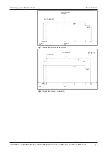
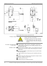
Page 12: ...eter Unit Value Permissible ambient temperature C F C F 5 41 to see Fig 1 0 32 if non condensing frost free Permissible media tem perature C F C F See Fig 2 Dimensions See Fig 5 Chapter 6 1 Installing...

Page 13: ...ting and Installation Instruction English KNF 316836 316838 06 22 13 Permissible ambient temperature Pressure in mbar Pressure in bar Fig 1 Permissible ambient temperature Permissible media temperatur...

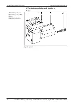
Page 14: ...N96_DC B M 14 Translation of Original Operating and Installation Instruction English KNF 316836 316838 06 22 4 Product description and function Design 1 Pneumatic pump inlet 2 Pneumatic pump outlet 3...

Page 15: ...4 3 6 5 Fig 4 Function of a diaphragm pump Diaphragm pumps transfer compress depending on the version and evacu ate gases and vapors The elastic diaphragm 4 is moved up and down by the eccentric 5 and...

Page 16: ...sk of injury from cutting on the sharp edges when grabbing corners or when opening the packaging Where appropriate wear suitable personal protective equipment e g safety shoes safety gloves Transport...

Page 17: ...ti bility of the media contacting components see 3 Technical data with the medium 6 1 Installing the pump Store the pump at the installation site to allow it to adapt to the ambient temperature before...

Page 18: ...llation make sure that no combustible or thermally de formable objects are positioned in the immediate proximity of the hot pump parts head drive Installation location Make sure that the installation...

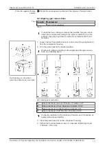
Page 19: ...gas connections pump head depicted as a example 1 Loosen the four head plate screws 1 and remove the pump head 2 from the compressor housing 2 Turn the pump head to the desired position Direction of...

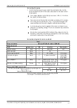
Page 20: ...ting If higher ESD requirements are needed measures are to be pro vided by the owner himself Refer to the type plate for the maximum current consumption of the pump Install an EMERGENCY OFF device suc...

Page 21: ...therwise be damaged Ensure the correct polarity With brushless three phase motors in dicated by a B at the end of the type designation incorrect polarity will result in destruction of the electronics...

Page 22: ...ion Instruction English KNF 316836 316838 06 22 Permissible control range Speed Fig 8 Cycle speed setpoint for N96KN_ Permissible control range Speed Fig 9 Cycle speed setpoint for N96KT_ For expanded...

Page 23: ...ischarge via the pneumatic outlet of the pump Decoupling KNF recommends mechanically decoupling the pump from the pipe system e g through the use of flexible hoses or pipes In this way it is possible...

Page 24: ...e hoses at the pneumatic connections Wear protective equipment if necessary e g safety gloves hearing protection WARNING Injury to eyes Coming too close to the inlet outlet of the pump may result in i...

Page 25: ...ntity on the pres sure line is throttled or regulated make sure that the maximum permissible operating pres sure at the pump is not exceeded Ensure that the pump outlet is not closed or restricted WAR...

Page 26: ...ion Speed without external speed setting The motor operates the pump with a non variable speed over the entire permissible pressure range see Connection diagram without speed set ting Speed with exter...

Page 27: ...ble legal regulations and pro cedures for the location or intervention by un trained or uninstructed personnel Servicing may only be performed according to the legal regulations e g work safety envi r...

Page 28: ...s The pump head or motor may still be hot after op eration of the pump Allow the pump to cool after operation WARNING Health hazard due to dangerous substances in the pump Depending on the medium bein...

Page 29: ...alve plates seals and diaphragm should generally be replaced at the same time If the diaphragm is not replaced at the same time as the valve plates seals the specified output of the pump can no longer...

Page 30: ...the power supply and check and ensure that the pump is voltage free b Remove pump head Loosen the four head plate screws 1 and remove the head plate 2 from the pump housing together with the intermedi...

Page 31: ...entical for the pressure and suc tion side the same applies for the top and bottom of the valve plates seals 4 By slightly moving the valve plates seals horizontally ensure that they are not under ten...

Page 32: ...d in the pump head Separate the source of the condensate from the pump Flush the pump with air at atmospheric pressure for a few minutes if necessary for safety reasons with an inert gas Install the p...

Page 33: ...es or pump head Eliminate the leaks Pneumatic connections or lines are completely or partially clogged Check the pneumatic connections and lines Remove any parts and particles that are causing blockag...

Page 34: ...2 Tab 20 see Chapter 8 3 Replacing diaphragm and valve plates Spare part set Order number N96KN_ 322637 N96KT_ 322636 N96ATDC B M 322636 N96STDC B M 326868 Tab 21 10 2 Accessories 1 2 3 3 2 4 5 6 Fig...

Page 35: ...pter 8 2 2 Cleaning the pump 4 Send the pump together with the completed Health and Safety Clear ance and Decontamination Form to KNF stating the nature of the transferred medium 5 Pack the device sec...

Page 36: ...KNF worldwide You can find our local KNF partners at www knf com...

Reviews: