background image


KNF Micro BA317001-316999 NMP830_HP-EN 0221.docx 
Translation of original Operating and Installation Instructions, English


Keep for future use 

Operating and Installation Instructions


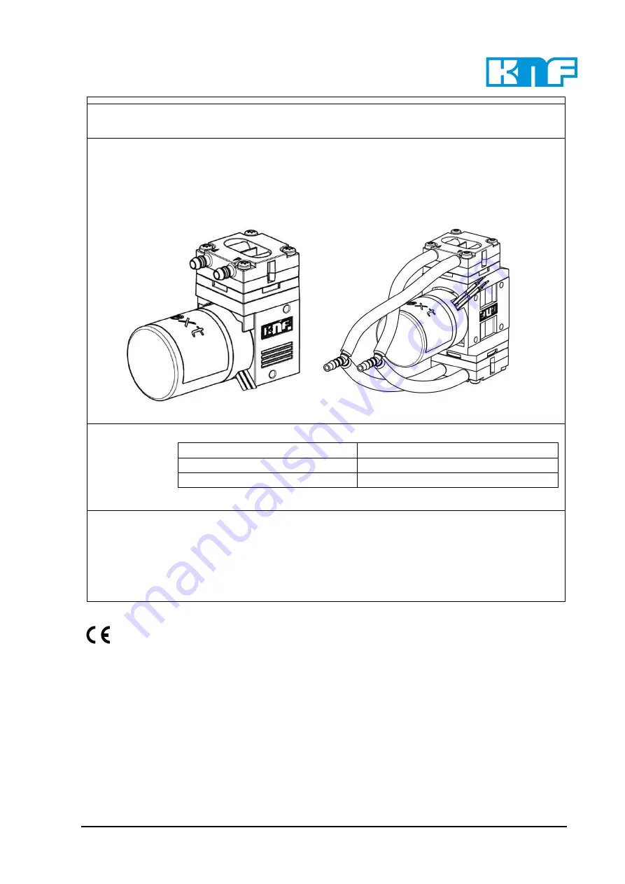
Micro Diaphragm Gas Sampling Pumps 


Type range: 

NMP830K_DC HP 


NMP830K_DC-B HP 

NMP830.1.2K_DC-B HP 


NMP830K_DC-B4 HP


NMP830.1.2K_DC-B4 HP 


You have selected a high-quality KNF product; the following tips will help you operate it safely, and 
reliably over a long period of time. Carefully study the Operating and Installation Instructions before 
using the pumps and observe at all times the relevant instructions to avoid dangerous situations. The 
manual  was  produced  for  the  serial  pumps  stated  above.  With  customer-specified  projects  (pump 
types starting with “PJM”, “PMM”, “PU” or “MPU“) there could be differences in detail. For customer-
specified projects please therefore take into account any agreed technical specifications, as well as 
these instructions.


Contents 

Page 

1.


About this document ................................................................. 2


2.


Use ........................................................................................... 3


3.


Safety ....................................................................................... 4


4.


Technical data .......................................................................... 6


5.


Assembly and function ........................................................... 10


6.


Operation ................................................................................ 13


7.


Servicing ................................................................................. 15


8.


Troubleshooting ...................................................................... 16


9.


Returns ................................................................................... 17


Product centre for 
micro pumps 

KNF Micro AG  
Zelglimatte 1b 
CH-6260 Reiden 
Switzerland 
Tel.   

+41(0) 62 787 88 88 

www.knf.com 

Summary of Contents for NMP830.1.2KPDC-B HP

Page 1: ...ructions before using the pumps and observe at all times the relevant instructions to avoid dangerous situations The manual was produced for the serial pumps stated above With customer specified projects pump types starting with PJM PMM PU or MPU there could be differences in detail For customer specified projects please therefore take into account any agreed technical specifications as well as th...

Page 2: ...is symbol indicates a potential danger It also indicates the possible consequences of fail ure to observe the warning The signal word e g Warning indicates the level of danger Here you will see actions for avoiding the dan ger and potential consequences Danger levels Signal word Meaning Consequences if not observed DANGER warns of immedi ate danger Consequences are death or se rious injury and or ...

Page 3: ...p head pump housing diaphragm seals and valves with the medium The temperature of the medium must lie within the permissible temperature range see Chapter 4 The transferred gas should not contain particles as these can pre vent the pump from working correctly If this cannot be guaranteed a filter 50 m with sufficiently large filter area must be used up stream of the pump See the type plate or data...

Page 4: ...ngerous media observe the safety regula tions for handling such media Be aware that the pumps are not designed to be explosion proof Make sure the temperature of the medium is always sufficiently be low the ignition temperature of the medium to avoid ignition or ex plosion This also applies for unusual operational situations Note that the temperature of the medium increases when the pump compresse...

Page 5: ...he provisions of the Machinery Directive 2006 42 EC The essential requirements of Annex I of Directive 2006 42 EC general principles are applied and observed General Principles No 1 No 1 1 2 1 1 3 1 3 1 1 3 3 1 3 4 1 4 1 1 5 8 1 5 9 1 7 4 1 7 4 1 1 7 4 3 As these partly completed machinery are OEM models the power supplies and the equipment for disconnecting and switching off the partly completed ...

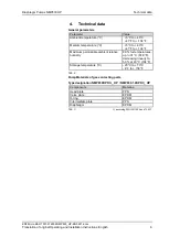
Page 6: ... F Medium temperature C 5 C to 40 C 41 F to 104 F Maximum permissible ambient relative humidity 80 for temperatures up to 31 C 87 8 F decreasing linearly to 50 at 40 C 104 F Storage temperature C 20 C to 70 C 4 F to 158 F Tab 2 Pump Materials of gas contacting parts Type designation NMP830KPDC _ HP NMP830 1 2KPDC_ HP Components Material1 Head plate PPS Valve plate EPDM O ring EPDM Intermediate pla...

Page 7: ...WG24 Protection class IP 54 Weight 1 g oz 170 6 Flow rate l min 2 3 5 Max operating pressure bar g psi g 2 3 3 0 43 5 Max vacuum mbar abs inHg 2 3 230 6 8 Tab 5 Characteristics NMP830KPDC B4 brushless B4 Brushless motor with internal electronic 4 wires Motor Variants Supply voltage V 5 12 24 Max current consumption A 0 85 0 45 Connection Wires AWG24 Protection class IP 54 Weight 1 g oz 170 6 Flow ...

Page 8: ...Characteristics NMP830 1 2KPDC B4 brushless 4 wires B4 Brushless motor with internal electronic and controllability Motor Variants Supply voltage V 5 12 24 Max current consumption A 1 5 0 8 Connection Wires AWG24 Protection class IP 54 Weight 1 g oz 230 8 1 Flow rate l min 2 3 4 9 Max operating pressure bar g psi 2 3 4 3 0 43 5 Max vacuum mbar abs inHg 2 3 4 230 6 8 Tab 8 1 The weight may differ s...

Page 9: ...n Lead color Signal name Size Supply voltage Red Vs AWG 24 Supply voltage Black Vs GND AWG 24 Speed control input signal White Vctrl AWG 24 Frequency output output signal Green FG AWG 24 DC control input Vctrl Control voltage range DC 0 5 VDC Resistant to surge voltages up to 28 VDC Threshold voltage 1 3 VDC FG frequency output FG pulses per mech revolution 18 Output level high Iout 0 1mA 4 2 5 4 ...

Page 10: ...ump due to automatic start If the pump overheats and the thermal switch electronics stops pump operation the pumps will restart automatically as soon as the motor has had time to cool down Take steps to ensure that this cannot produce a haz ardous situation 5 2 Electrical connection Only have the pump connected by an authorized specialist Only have the pump connected when the power supply is dis c...

Page 11: ...ses that are chemically resistant to the media be ing pumped If ambient air is sucked in use a filter to protect pump from dust 5 3 1 Connecting the pump Arrows on the pump head indicate the flow direction 1 Remove the protective caps from the hose connections 2 Connect the suction and pressure lines 3 If the pump is used to build up pressure make sure that all transition joints between hose and p...

Page 12: ... Instructions English 12 5 4 Fixation Fixation for NMP830 HP The pump offers two mounting points which allow an easy fixation of the pump with either 2x Delta PT35 or 1x Delta PT35 and 1x DIN912 M3 screws Fixation for NMP830 1 2 HP The pump has four mounting points which allow an easy fixation of the pump with 4x Delta PT35 or 4x DIN912 M3 screws ...

Page 13: ...g The drive heats up Avoid contact with the pump drive Avoid contact with flammable materials Excessive pressure and the inherent dangers thereof can be prevented by placing a bypass line with a pressure relief valve between the pressure and suction side of the pump Please contact your local KNF partner for further information www knf com If the pump stops running restore the system to normal atmo...

Page 14: ...7 3 psi NMP830KPDC HP NMP830 1 2KPDC B HP NMP830 1 2KPDC B4 HP respective over 0 7barg 10 2 psi NMP830KPDC B HP und NMP830KPDC B4 HP the duty cycle must be restricted During operation a maximum temperature of 90 C should not be exceeded in the pump head EPDM components The tempera ture must be measured on the pressure side of the pump head For higher temperatures FKM components are recommended Mea...

Page 15: ...s these may corrode certain plastic or metallic parts Isolate the pump from the power supply Pump must be free of any hazardous substances Hoses must be disconnected from the pump 7 3 Service interval For operation above defined borders in Chapter 6 Duty Cycle maintenance intervals are recommended For Service Spare part kit ID 317273 is available Contained parts Diaphragm 1pcs O Ring 2pcs Valve pl...

Page 16: ...system connected to the suction and pressure sides such as hoses valves or filters are causing too much resistance Modify installation check the cross sections of components Hose connections are not leak tight Secure transition joints between hose and hose connections with clamps or clamping elements Particles in the pump Clean the pump head install suction side filter if required Incorrect interc...

Page 17: ...the pump 3 Clean the pump see the Chapter Cleaning the pump 4 Send the pump together with completed Health and Safety Clear ance and Decontamination Form to KNF stating the nature of the transferred medium 5 Package the device securely to prevent further damage to the product If necessary request an original packaging at a charge Returns KNF shall undertake to repair the pump only under the condit...

Page 18: ...aphragm Pumps NMP830 HP KNF Micro BA317001 316999 NMP830_HP EN 0221 docx Translation of original Operating and Installation Instructions English 18 KNF worldwide Find our local KNF partner on www knf com ...

Page 19: ...Diaphragm Pumps NMP830 HP KNF Micro BA317001 316999 NMP830_HP EN 0221 docx Translation of original Operating and Installation Instructions English 19 ...

Reviews: