background image


Operating and Installation Instructions


Swing Piston 

Compressors and 

Vacuum Pumps


Type Range: 

UNPK09  

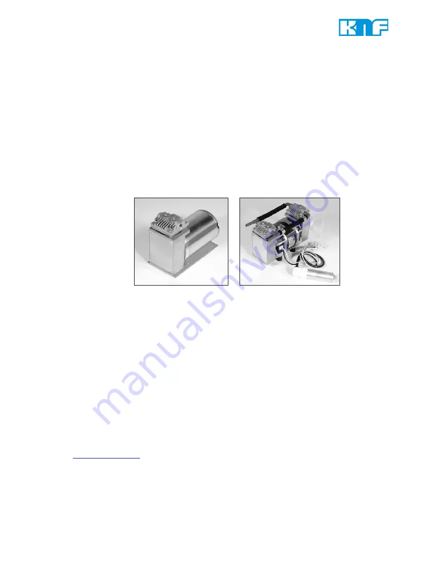
UNPK09.1 


UNPK09DC 


UNPK09.2 


UNPK09.1.2 


                                                 Fig. 1: UNPK09                                   Fig. 2: UNPK09.1.2 

You have selected a high-quality KNF product; the following tips will help you operate it safely and reliably 
over a long period of time. Carefully study the Operating and Installation Instructions before using the 
pumps and observe at all times the relevant instructions to avoid dangerous situations. The manual was 
produced for the serial pumps stated above. With customer-specified projects (pump types starting with 
“PU“ or “MPU“) there could be differences in detail. For customer-specified projects please therefore take 
into account any agreed technical specifications, as well as these instructions.


List of Contents 

Page 

1.


Description, Operating Conditions ........................................... 2


2.


Safety ...................................................................................... 3


3.


Installation ...............................................................................  4


4.


Operation ................................................................................ 5


5.


Servicing ................................................................................. 6


6.


Cleaning ................................................................................  10


7.


Trouble Shooting ................................................................... 11


8.


Spare parts ........................................................................... 12


9.


Accessories ........................................................................... 12


10.


Tables ...................................................................................  13


11.  Product Return.......................................................................14 


KNF Neuberger, Inc 
2 Black Forest Rd 
Trenton, NJ 08691-1810 
 
Phone: 609-890-8600 
Fax:  

609-890-8323 


www.knf.com/usa.htm


Ident#121576-125598 
Revision (09/12) 

Summary of Contents for UNPK09

Page 1: ...ns The manual was produced for the serial pumps stated above With customer specified projects pump types starting with PU or MPU there could be differences in detail For customer specified projects please therefore take into account any agreed technical specifications as well as these instructions List of Contents Page 1 Description Operating Conditions 2 2 Safety 3 3 Installation 4 4 Operation 5 ...

Page 2: ...sors and vacuum pumps must not be used for liquids You will find suitable liquid pumps in our Product Program For maximum permissible operating pressure ultimate vacuum and flow capacity see section 10 The KNF swing piston compressors and vacuum pumps must not be used in areas where there is a danger of explosion If your potential application lies outside the above limits discuss it with our techn...

Page 3: ...upted by the thermal switch the pump will re start auto matically after cooling down Take all care necessary to prevent this leading to a dangerous situation Use only original KNF spare parts Pumps in the NPK 09 range conform to the safety regulations of the EC Low Voltage Directive 2006 95 EC and of the EC Directive 2004 108 EC concerning Electromagnetic Compatibility For the purposes of the Mach...

Page 4: ...by more than 10 and 10 from that shown on the type plate The earth ground wire must be connected to the motor not necessary on dc motors up to 24 V For brushed dc motor lead wires connection Red V Black Ground Î Incorrect lead wire connection will damage motor For brushless dc motor lead wire connection Red V Black Ground White Voltage control 0 5 V DC 4 wire motor only Green Frequency output 4 wi...

Page 5: ...n or control of the air or gas flow should only be carried out in the suction line If restriction or control of the air or gas flow is made on the pres sure side ensure that the maximum permissible operating pressure is not exceeded When the pump is at a standstill the inlet and exhaust must be at normal atmospheric pressure Change the filter accessories if it is dirty The piston seals and to a le...

Page 6: ...r damage tongues bent corrosion The position numbers in the following text refer to figs 3 to 6 Fig 3 Pump element single head types Fig 4 Pump element twin head types Fig 5 Pump element all types Fig 6 Pump head all types Specifiaction Pos Description 1 Housing 2 Intermediate plate 3 Ribbed head 4 Screw 5 Connection only twin head models 6 Gasket 7 Valve Plate 8 Valve Plate 9 O Ring 10 Cylinder 1...

Page 7: ...emove gasket 6 valve plate 7 intermediate plate 2 and valve plate 8 from housing 1 5 Only for the pump model NPK09 DC Take off the cover 18 after removing the 4 screws securing it For this pump type applies Where reference is made to turning or holding the cooling fan the necessary operations must be carried out by turning or holding the counter weight 17 6 Turn the fan to bring the retainer plate...

Page 8: ...th valve plates are identical and they can be fitted either way up The intermediate plate can also be fitted either way up 6 Place the head assembly on the pump housing 1 as a guide to orientation see fig 3 single head models or fig 4 twin head models Reference point is the compression symbol indicated with a K in the diagrams or the mark M 7 Tighten the screws 4 at first lightly then firmly by ha...

Page 9: ...using new valve plates 2 for each head For twin head pumps repeat the operations described for the second head and replace the connections between the two heads If after changing the valve plates the specified vacuum is not reached check the following pneumatic connections for tightness for twin head models that the head connections are gas tight If after changing the valve plates the pump produce...

Page 10: ... inspect all parts for dirt before assembling the pump head and clean them if necessary As far as possible clean the parts with a dry cloth Solvents should not be used as they can attack the plastics and synthetic rubber parts If a compressed air line is available blow the parts out with it ...

Page 11: ...ure or vacuum too low Compare the actual performance with the figures in section 10 or the data sheet There is pressure on the pressure side and at the same time vacuum or a pressure above atmospheric on the suction side The pump is not designed for this condition The internal diameter of connecting tubing or connected components or connected components is too small or they are restricted In order...

Page 12: ...n side Connection for NPK 09 2 NPK 09 1 2 pressure side 026178 026179 6 Gasket 052650 7 8 Valve plate 052649 9 O Ring 025547 10 Cylinder 025528 11 Retainer Plate 025530 12 Support 025532 13 Piston seal 025531 14 Screw 110725 15 Washer 006886 Tab 6 Spare Parts according to figure 5 9 Accessories Description Order No Silencer Filter 072233 Hose Connector 1 8 MPTM HID 072235 Tab 7 Accessories ...

Page 13: ...0 Tables Pump type Max permissible operating pres sure bar g Ultimate vacuum mbar abs Delivery rate l min at atm pressure UNPK09 7 100 12 UNPK09DC 7 100 15 UNPK09 1 100 24 UNPK09 2 7 24 UNPK09 1 2 7 100 24 Tab 8 Pneumatic Data Litre at STP ...

Page 14: ...an RMA number submit a completed Decontamination Declaration form to rma knf com Î The Decontamination Declaration form can obtained from our website or by contacting KNF Technical Services http www knf com pdfs decontamdec doc Phone 609 890 8600 Î Product return instructions will be provided when the RMA is issued KNF Neuberger Inc 2 Black Forest Rd Trenton NJ 08691 1810 Phone 609 890 8600 Fax 60...

Page 15: ......

Page 16: ......

Reviews: