KNIGHT D-SERIES SERVO HOIST OPERATION MANUAL
SECTION 2
INSTALLATION
9
Step 2d) 4mm and 5mm Chain Installation:
CAUTION
DO NOT CUT CHAIN TO SHORTEN IT! The chain will be reeled into the
hoist in Section 2, Step 5 “Control Handle Set-up”.
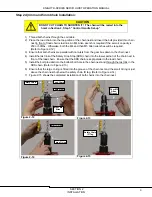
1) Thread both chains through the coil cable.
2) Place the load chain into the top portion of the chain nest and insert the bolt provided thru chain
nest in front of load chain’s last link. An M4 Allen wrench is required if the servo’s capacity is
250 or 500lbs. Otherwise, both the M4 and then M5 Allen wrenches will be required.
(Refer to Figure 2-12)
3) Ensure that both chains are parallel with no twists from the gear box down to the chain nest.
4) Install the last link of the Safety Drop Stop (SDS) chain into the lower portion of the chain nest in
front of the load chain. Ensure that the SDS chain is kept parallel to the load chain.
5) Install the bolt provided into the bottom bolt hole in the chain nest and through the last link in the
SDS chain. (Refer to Figure 2-13)
6) Ensure that the large O-ring is fitted into the groove of the chain nest and the small O-ring is just
above the chain nest but below the safety chain ID tag. (Refer to Figure 2-14)
7) Figure 2-15 shows the completed installation of both chains into the chain nest.
Figure 2-12
Figure 2-13
Figure 2-14
Figure 2-15
Chain Nest
M4 or M5
Allen
Wrench
M4 or M5
Allen
Wrench
Small O-ring
Large O-ring
Load Chain
Safety Chain
Safety Chain
ID Tag


