KNIGHT D-SERIES SERVO HOIST OPERATION MANUAL
SECTION 4
MAINTENANCE
30
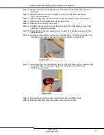
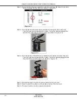
Step 11. While supporting the chain buckets, remove the (1) one M5 retainer bolt that
secures both chain buckets inside of the Servo Hoist. (Refer to Figure 4-11)
Figure 4-11
Step 12. Remove both chain buckets through the bottom of the Servo Hoist.
Step 13. Remove both chains from their individual chain buckets.
Step 14. Remove both of the end-stop assemblies from the each of the old load and
Safety Drop Stop (SDS) chains.
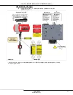
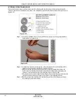
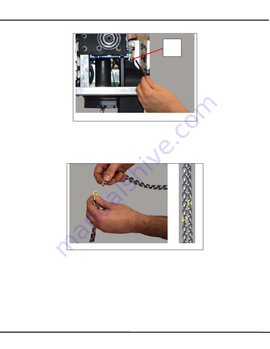
Step 15. Connect both of the old chains together with the both of new chains by using both of
the yellow chain interface links. (Refer to Figure 4-12)
Figure 4-12
Step 16. Power the system back up.
Step 17. To enable the chain pay-out sequence, using the Operator Control Interface (OCI),
twist the Run-Stop button clockwise to enable the hoist.
Within 3 seconds, press the Run-Stop button, press and release the Green Lift
button and then the Blue Float button, twist the Run-Stop button clockwise and
release. This will start the pay-out mode after three to ten seconds.
If the direction is incorrect, press the Run-Stop button to stop the pay-out mode and
repeat the above sequence to pay-out the chain in the opposite direction.
Step 18. Stop the pay-out mode by pressing the Run-Stop button when the yellow interface
chain links have moved through the gear box and are at an acceptable height to
reattach the inline handle.
Chain
Bucket
retainer
bolt

