background image

Page 4 of 12 

0901177 Rev: A (10/15) 

INSTALLATION 

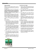
Mount the unit (using suitable hardware) with the 
provided bracket in the accessory kit. Try to keep the 
unit within three feet from the final rinse line to avoid 
long tubing runs. 

CAUTION: Do not mount the unit in the direct path 
of steam. This can short circuit and permanently 
damage the unit. Mounting the unit on the side, on 
the back, or on the vents of the dishwasher may 
cause thermal overload and damage or hinder the 
performance of the unit. 

Check all applicable plumbing and electrical codes 
before proceeding with the installation. This will help to 
ensure that the system is installed in safe and suitable 
manner. A wiring schematic of the dishwasher should 
be used as reference for making electrical connections 
— this is typically provided by the dishwasher 
manufacturer if one cannot be located on the machine 
itself. 

Rinse Plumbing 

(1)  Install the provided 1/4" tube x 1/8" NPT injection 

fitting into the side or bottom of the dishwasher 
rinse line between the rinse solenoid valves and the 
rinse jets. If necessary, drill a 11/32" hole and tap to 
1/8" NPT. Use of a saddle clamp may be desired on 
copper rinse line for better support. 

(2)  Cut a suitable length of 1/4" OD poly tubing and 

connect between the discharge (right) side of the 
rinse pump’s squeeze tube and the injection fitting.  
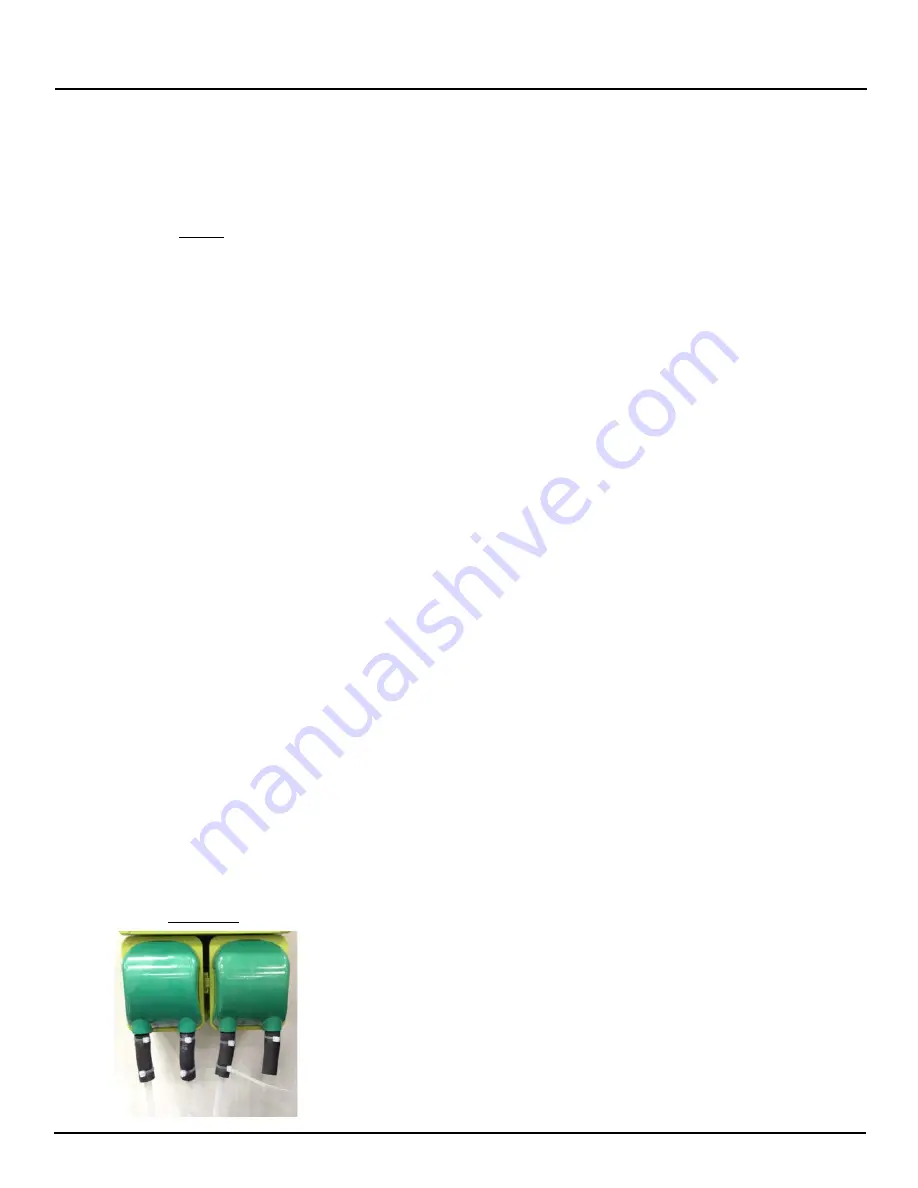
Cut 2” of the supplied T-50EH tubing (7018061) 
and zip tie the tubing to the pump suction and 
discharge fitting. (See Diamgram A below).  Use 
the T-50EH tubing to connect poly tube to the pump 
fitting. 

(3)  Cut a suitable length of 1/4" OD poly tubing and 

connect between the suction (left) side of the rinse 
pump’s squeeze tube and the pickup tube provided. 
Be sure to draw tubing through the end of the 
pickup tube. 

(4)  Hand-tighten the compression nuts on both the 

rinse fitting and pickup tube. Plastic ties can be 
used to cinch around the connections where the 
poly tubing is inserted into the pump’s squeeze 
tube. 

Liquid Detergent Plumbing 

(1)  Install the provided bulkhead fitting through a wall 

of the wash tank (above water level). If an existing 
mounting hole cannot be located, use of a 7/8" hole 
saw or punch may be desired. 

(2)  Cut a suitable length of 1/4" OD poly tubing and 

connect between the discharge (right) side of the 
detergent pump’s squeeze tube and the bulkhead 
fitting. 

(3)  Cut a suitable length of 1/4" OD poly tubing and 

connect between the suction (left) side of the 
detergent pump’s squeeze tube and the pickup 
tube provided. Be sure to draw tubing through the 
end of the pickup tube. 

(4)  Hand-tighten the compression nuts on both the 

bulkhead fitting and pickup tube. Plastic ties can be 
used to cinch around the connections where the 
poly tubing is inserted into the pump’s squeeze 
tube. 

Dry Detergent Plumbing 

(1)  A powder or solid type feeder (not provided) should 

be used for dispensing dry detergent products. 
Follow the instructions included with the detergent 
feeder for installation, and recommended water 
temperature/pressure. 

(2)  Cut a suitable length of 1/4" OD copper tubing (not 

provided) and connect between the input side of the 
water solenoid and the water source. Maximum 
recommended water temperature is 140°F (60°C). 

(3)  Cut a suitable length of 1/4" OD copper tubing (not 

provided) and connect between the output of water 
solenoid to a powder or solid detergent feeder. 

(4)  Carefully tighten the compression nuts on the water 

solenoid — over tightening may cause  solenoid to 
leak. Tighten connections to the water source and 
detergent feeder as needed. 

INSTALLATION 

Diagram A


Summary of Contents for UMP Hospitality

Page 1: ...tality Instruction Manual TABLE OF CONTENTS Settings Guide 2 Installation Diagram 3 Dimensions 3 Accessory Kit 3 Installation 4 Electrical 5 Operation 6 Programming 7 Parts Diagram 9 Wiring Diagram 10 Warranty Information 12 Knight Locations 12 ...

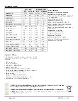
Page 2: ...0 999 0 999 0 999 DETERGENT PULSE 10 90 10 90 NO NO DETERGENT PULSE RATE 3 15s 3 15s NO NO SETTINGS GUIDE Default Settings System is in Conductive Probe Mode System is set for Door Machines Detergent Pulse Rate is 5 Seconds dry or 3 Seconds liquid Default Password is 0000 Rinse Pump Speed is 50 Detergent Concentration Setpoint is 25 Detergent Alarm Delay is set to 64 Seconds Rinse Limit is 30 Seco...

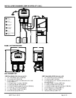
Page 3: ...uction Manual 0901177 INSTALLATION DIAGRAM UMP HOSPITALITY 200L MAIN UNIT DIMENSIONS UMP Hospitality 200D Accessory Kit 1 1 4 Poly tubing 20 ft 7028109 2 1 x Pick up tube 7020180 3 2 x Expansion screw includes wall anchor and screw 7600121 4 1 x Check Valve 1 4 tube 7901350 5 1 x Fitting Bulkhead Ell 7023342 6 1 x Probe includes gasket nut lock 7005190 7 2 x Tie Wrap 3 5 in long 0300121 8 Tube T 5...

Page 4: ... and the pickup tube provided Be sure to draw tubing through the end of the pickup tube 4 Hand tighten the compression nuts on both the rinse fitting and pickup tube Plastic ties can be used to cinch around the connections where the poly tubing is inserted into the pump s squeeze tube Liquid Detergent Plumbing 1 Install the provided bulkhead fitting through a wall of the wash tank above water leve...

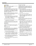
Page 5: ...ch into the drilled tapped hole 4 Wire the pressure switch per the appropriate wiring diagram on page 10 Detergent Power Signal A detergent power signal is required to activate the detergent probe sensing or probeless initial charge The detergent signal can be jumpered from main power for applications where the main power is controlled by the on off state of the dishmachine 1 Check the dishwasher ...

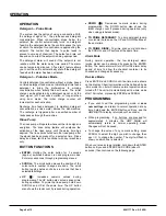
Page 6: ...un and program modes Enter also advances through programming menus SCROLL The scroll button moves the position of the cursor where number changes are done The scroll button toggles between choices in menus that have selectable settings UP Increases numeric values during programming The UP button also acts as rinse prime during operation To prime the rinse pump hold down SCROLL and UP at the same t...

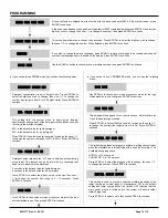
Page 7: ... 0 to 30 Press ENTER to continue RACK TIME 000 This setting tells the system when to begin pulse feeding specifically at what percent of the detergent concentration you have just set in the previous display 85 is the default value for liquid detergent 50 is the default value for dry detergent Press SCROLL to select the digit you wish to change then use to change the number the range is 10 to 90 Pr...

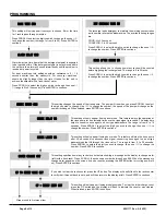
Page 8: ...number the speed of the pump will change as the number is changed When finished press ENTER to continue RINSE SPEED 050 This setting will only appear if using door mode This feature will stop the rinse pump after XX seconds of continuous rinse signal conserving rinse agent on door type dishmachines that fill through the rinse valve The range is from 0 to 30 seconds Press SCROLL to select the digit...

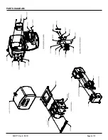
Page 9: ...0901177 Rev A 10 15 Page 9 of 12 PARTS DIAGRAM ...

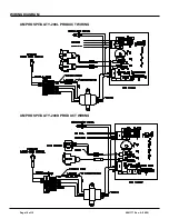
Page 10: ...Page 10 of 12 0901177 Rev A 10 15 UMP HOSPITALITY 200L PRODUCT WIRING UMP HOSPITALITY 200D PRODUCT WIRING WIRING DIAGRAM ...

Page 11: ...0901177 Rev A 10 15 Page 11 of 12 NOTES ...

Page 12: ...ctive upon factory authorized inspection Bearings and pump seals or rubber and synthetic rubber parts such as O rings diaphragms squeeze tubing and gaskets are considered expendable and are not covered under warranty Warranty does not cover liability resulting from performance of this equipment nor the labor to replace this equipment Product abuse or misuse voids warranty FOOTNOTE The information ...

Reviews: