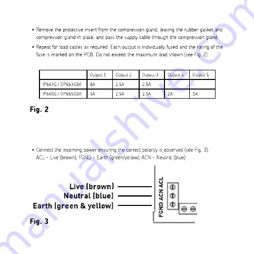
Output 1
Output 2
Output 3
Output 4
Output 5
IP663G / OP663GBK
8A
2.5A
2.5A
-
-
IP665G / OP665GBK
5A
2.5A
2.5A
2A
1A
Fig. 3
•
Connect the various loads ensuring correct polarity is observed (see Fig. 4): ACL - Live (brown), FGND -
Earth (green/yellow), ACN - Neutral (blue)
Fig. 4
•
Secure the cables in place via the cable clamps, then tighten the compression glands ensuring a good
seal is made around each cable
•
Switch on power to the unit, ensuring it is safe to do so
•
See below for matching the remote control to the switch box
•
Refasten the cover and secure with the screws provided - do not overtighten
•
Check for correct operation
REMOTE CONTROL SETUP
•
Remove the battery cover from the remote control, insert a 1.5V AAA battery (not included) and replace
the cover
•
Press and release the "MATCH" switch on the circuit board (see Fig. 1), the green LED indicator will flash
•
Press and hold any button on the remote control until the LED indicator on the circuit board is stable and
not flashing
•
Press the "ON" button on channel 1 of the remote control, the red channel 1 indicator on the box cover will
illuminate
•
Once channel 1 is programmed the other channels will be set up automatically, the product is now ready
for use
•
A new remote control can be matched to the switch box by following the procedure above. It is not
possible to match two remotes to the same switch box, as matching the second remote unmatches the
first
•
It is possible to match two switch boxes simultaneously onto the same remote, but then the two channel
1s / channel 2s etc can only be switched together
WARNING
This product must be disconnected from the circuit if subjected to any high voltage or insulation resistance testing.
Irreparable damage will occur if this instruction is not followed.
The remote control is not weatherproof.
GENERAL
This product should be recycled in the correct manner when it reaches the end of its life. Check local authorities for
where facilities exist.


