background image

GENEral

3

Status: 17.05.22

1  General

1.1  Notes on operating instructions

These operating instructions are designed to enable you to use your tool 

safely and efficiently.

The tool may only be used if it is in technically perfect condition.
As a consequence of technical developments, the illustrations and descrip-
tions contained in these operating instructions may differ slightly from the 
tool actually delivered.
We do not accept any liability for damage caused by failure to observe these 
operating instructions.

1.2  Symbols used

All safety instructions in these operating instructions are indicated by corre-
sponding symbols. The signal words at the beginning of each safety instruc-
tion express the extent of the Hazard.

Danger!

Danger of severe to fatal injury

This combination of symbol and signal word indicates an imminently haz-
ardous situation that will result in death or serious injury if not avoided.

Warning!

Warning of potentially serious to fatal injury

This combination of symbol and signal word indicates a possibly hazardous 
situation that may result in death or serious injury if not avoided.

Caution!

Risk of minor injury

This combination of symbol and signal word indicates a dangerous situation 
that can lead to minor or moderate injury.

Notice!

Indicates possible damage to property or the environment

This combination of symbol and signal word stands for important informa-
tion that helps to prevent damage to property or the environment.

1.3  Copyright

These operating instructions and all documentation supplied with this tool 
are protected by copyright and remain the property of KNIPEX.
The reprinting of these instructions, even in extract form, is only permitted 
with the written consent of C. Gustav Putsch KG.

Summary of Contents for 12 72 190

Page 1: ...KNIPEX Quality Made in Germany EN KNIPEX NexStrip Multi Tool for Electricians Operating instructions 12 72 190 5 10 15 20...

Page 2: ...3 Copyright 3 1 4 Guarantee and warranty 4 2 Safety 4 2 1 Intended use 4 3 Design and function 5 3 1 Design 5 3 2 Function 5 4 Operation 6 4 1 Cutting cables 6 4 2 Stripping cables 6 4 3 Crimping wir...

Page 3: ...s combination of symbol and signal word indicates an imminently haz ardous situation that will result in death or serious injury if not avoided Warning Warning of potentially serious to fatal injury T...

Page 4: ...t by unauthorized persons Original accessories or spare parts from KNIPEX are not used Defective components are not repaired immediately to minimise the extent of the damage and so as not to impair th...

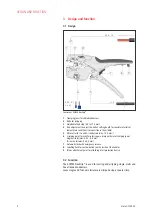
Page 5: ...o position in the middle 5 Wire cutter for Cu and Al conductors max 10 0 mm 6 Crimping point for wire ferrules square crimp with metal crimping jaws Single wire ferrules 0 25 4 0 mm Twin wire ferrules...

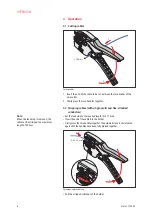
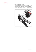
Page 6: ...multi and fine stranded conductors Set the feed stop to the required length 3 to 17 mm Insert the end of the cable into the holder Firmly press the two handles together The automatic lock is not rele...

Page 7: ...tion materials that are difficult to work with or if there are special temperature conditions it may be necessary to adjust the cutting depth Push the fine adjustment slider in the or direction to ind...

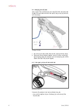
Page 8: ...1 Insert the wire ferrule and the cable into the crimping die from below 2 Firmly press the two handles together In order to ensure consistently high crimping quality the automatic lock is not releas...

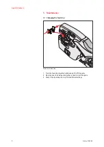
Page 9: ...5 1 Changing the feed stop Replacing the feed stop 1 Press the feed stop together lightly and pull it off the guide 2 Place the new feed stop on the guide so that it clicks into place 3 Check if the f...

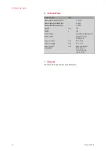
Page 10: ...pare length stop 12 49 23 Length mm 195 Weight g 166 Material body Glass fibre reinforced plastic Material blade Special tool steel oil hardened Capacity cutting mm 0 03 10 0 Capacity stripping mm 0 0...

Page 11: ...11 Status 17 05 22...
Page 12: ...KNIPEX Werk C Gustav Putsch KG 42337 Wuppertal Tel 49 202 47 94 0 Fax 49 202 47 74 94 info knipex com www knipex com...

Reviews: