2
Knorr-Bremse Group
PD-203-500
Doc. No. Y250905 (EN - Rev. 000)
July 2016
The information contained herein is subject to alteration without notice and therefore may not be the latest release. Please check our website www.knorr-bremseCVS.com for the latest update or contact your local Knorr-Bremse representative.
The figurative mark “K” and the trademarks KNORR and KNORR-BREMSE are registered in the name of Knorr-Bremse AG. Additional terms and conditions apply; please refer to our website knorr-bremseCVS.com for full Disclaimer.
Note: If service work is carried out on a vehicle based on information provided herein, it is the responsibility of the workshop to ensure the vehicle is fully tested and in full
functional order before the vehicle is returned into service. Knorr-Bremse accepts no liability for problems caused as a result of appropriate tests not being carried out.
Copyright © Knorr-Bremse AG - all rights reserved, including industrial property rights applications. Knorr-Bremse AG retains any power of disposal, such as for copying and transferring.
Knorr-Bremse Systeme für Nutzfahrzeuge GmbH . Moosacher Straße 80 . 80809 Munich . Germany . Tel: +49 89 3547-0 . Fax: +49 89 3547-2767 . www.knorr-bremse.com . www.knorr-bremseCVS.com
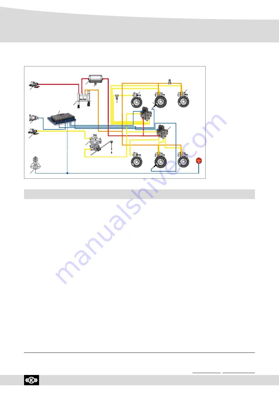
KB4TA D System Overview
P r o d u c t D a t a
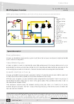
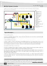
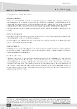
Legend:
1 Coupling Head with Filter -
“Supply”
2 Coupling Head with Filter -
“Control”
3 ABS-Connector ISO 7638
4 Park-/Shunt Valve with
EmergencyFunction
5 Air Reservoir
6 Drain Valve
7 Load Sensing Valve
8a ABS ECU
8b ABS Relay Modulator Valve
9 Brake Chamber
10 Spring Brake
11 Sensing Ring and Wheel Speed
Sensor
14 Test Connector
15 Electrical Connector “Lighting”
acc. to ISO 1185
KB4TA D System diagram (2S/2M) for semi-trailer with mechanical suspension and drum brakes
(ECU mounted at front of trailer)
11
SER
VI
CE
PARKI
N
G
12
11
SER
VI
CE
PARKING
12
11
SER
VI
CE
PARKI
N
G
12
11
SER
VI
CE
PARKING
12
kb4tad_sys__002
1
2
3
15
5
6
4
14
9
10
7
11
8a
8b
Power up Sequence
At power up, the KB4TA D ECU performs a series of self-checks that can assist a technician to determine the ABS
system status and configuration.
Trailer ABS Warning Lamp
At power up (when no faults are detected) the trailer ABS warning lamp in the towing vehicle will turn on for
approximately 2 seconds as a bulb check and then turn off. If a fault has been detected the bulb will remain on. The
same warning lamp sequence is produced by the trailer mounted headboard warning lamp (when installed)
Modulator ‘Chuff Test’ at Power up
At power up, the KB4TA D ECU activates a modulator ‘chuff test’. This electrical and pneumatic ABS modulator test
can help the technician identify problems with modulator installations and/or wiring.
With brake pressure applied, a properly installed modulator will generate five rapid audible ‘chuffs’ of air pressure on
the left internal modulator followed by five ‘chuffs’ on the right modulator. There will then be five further ‘chuffs’ on
the additional axle modulator if fitted .
If the ECU is wired incorrectly, the modulator will only produce one ‘chuff’, or no ‘chuffs’ at all. If a fault is detected
during the modulator ‘chuff test’, compare the wiring and piping to the electrical system schematic and make any
necessary alterations.
System Description
Y026787: 006: EN: Released: Fri Nov 11 11:18:50 CET 2016:


