4
Knorr-Bremse Group
PD-203-430
ES1305
Doc. No. Y250906 (EN - Rev. 000)
July 2016
The information contained herein is subject to alteration without notice and therefore may not be the latest release. Please check our website www.knorr-bremseCVS.com for the latest update or contact your local Knorr-Bremse representative.
The figurative mark “K” and the trademarks KNORR and KNORR-BREMSE are registered in the name of Knorr-Bremse AG. Additional terms and conditions apply; please refer to our website knorr-bremseCVS.com for full Disclaimer.
Note: If service work is carried out on a vehicle based on information provided herein, it is the responsibility of the workshop to ensure the vehicle is fully tested and in full
functional order before the vehicle is returned into service. Knorr-Bremse accepts no liability for problems caused as a result of appropriate tests not being carried out.
Copyright © Knorr-Bremse AG - all rights reserved, including industrial property rights applications. Knorr-Bremse AG retains any power of disposal, such as for copying and transferring.
Knorr-Bremse Systeme für Nutzfahrzeuge GmbH . Moosacher Straße 80 . 80809 Munich . Germany . Tel: +49 89 3547-0 . Fax: +49 89 3547-2767 . www.knorr-bremse.com . www.knorr-bremseCVS.com
KB4TA ABS Module
P r o d u c t D a t a
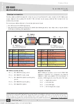
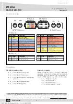
Electrical connections
Pin
Signal
Connection
X1-1
AUXI01
Auxiliary Input/Output
(4S/3M: Valve 3rd Modulator)
X1-2
AUXRET23
Return Line for AUXI02 and AUXI03
(Diagnostics Ground)
X1-3
TI_CANL
5V-CAN Low for Diagnostics
X1-4
GND_M
System Ground
(ISO 7638 - ABS connector - Pin 4)
X1-5
TI_CANH
5V-CAN High for Diagnostics
X1-6
BAT
Valve Supply Voltage
(ISO 7638 - ABS connector - Pin 1)
Pin
Signal
Connection
X1-7
GND_H
Warning Lamp Ground
(ISO 7638 - ABS connector - Pin 3)
X1-8
WL
Warning Lamp
(ISO 7638 - ABS connector - Pin 5)
X1-9
IGN
ECU Supply Voltage
X1-10
AUXI03 (DIA)
Auxiliary Input/Output
(Diagnostics Supply Voltage)
X1-11
AUXI02/
GND_BL
Auxiliary Input/Output
(Stop lamp ground)
X1-12
AUXRET1/BL
Return Line for AUXI01
(Stop lamp Supply)
(4S/3M: Return Line 3rd Modulator)
SL − Left Sensor
SAL − Additional Left Sensor for
4S/2M and 4S/3M configurations
SR − Right Sensor
SAR − Additional Right Sensor for
4S/2M and 4S/3M configurations
X1 - Code A
(grey connector)
ISO 7638 Connection (5 Pins)
X1-4 = ISO 7638 Pin 4 valve ground
X1-6 = ISO 7638 Pin 1 valve supply
X1-7 = ISO 7638 Pin 3 ignition / warning lamp
ground
X1-8 = ISO 7638 Pin 5 warning lamp
X1-9 = ISO 7638 Pin 2 ignition
Diagnostic Connector
KB4TA harnesses provide a 4-pin 5 Volt J1939 CAN
diagnostic connection for a diagnostic tool. Remote
diagnostic cables are available from Knorr-Bremse to
provide a J1939 diagnostic port at the side of the trailer.
X1-2 = Diagnostics ground
X1-3 = 5 Volt CAN low
X1-5 = 5 Volt CAN high
X1-10 = 24 Volt diagnostics supply
The Knorr-Bremse KB4TA module ECU connectors use a 12-pin Deutsch DT series connector for ISO 7638 power
supply, diagnostics and auxiliary I/Os like ISO 1185 stop lamp power supply, additional third modulator and one
additional Input/Output.
The module also utilizes either two or four wheel speed sensor inputs:
• SL & SR are used for 2S/2M applications.
• SAL and SAR are additional connections for 4S/2M and 4S/3M applications, note: these sensors may be installed
on lift axles in certain system applications.
Y026787: 006: EN: Released: Fri Nov 11 11:18:50 CET 2016:

