6
Knorr-Bremse Group
PD-203-530
ES1220
Doc. No. Y250907 (EN - Rev. 001)
September 2016
The information contained herein is subject to alteration without notice and therefore may not be the latest release. Please check our website www.knorr-bremseCVS.com for the latest update or contact your local Knorr-Bremse representative.
The figurative mark “K” and the trademarks KNORR and KNORR-BREMSE are registered in the name of Knorr-Bremse AG. Additional terms and conditions apply; please refer to our website knorr-bremseCVS.com for full Disclaimer.
Note: If service work is carried out on a vehicle based on information provided herein, it is the responsibility of the workshop to ensure the vehicle is fully tested and in full
functional order before the vehicle is returned into service. Knorr-Bremse accepts no liability for problems caused as a result of appropriate tests not being carried out.
Copyright © Knorr-Bremse AG - all rights reserved, including industrial property rights applications. Knorr-Bremse AG retains any power of disposal, such as for copying and transferring.
Knorr-Bremse Systeme für Nutzfahrzeuge GmbH . Moosacher Straße 80 . 80809 Munich . Germany . Tel: +49 89 3547-0 . Fax: +49 89 3547-2767 . www.knorr-bremse.com . www.knorr-bremseCVS.com
KB4TA D ABS ECU
P r o d u c t D a t a
Installation
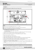
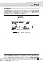
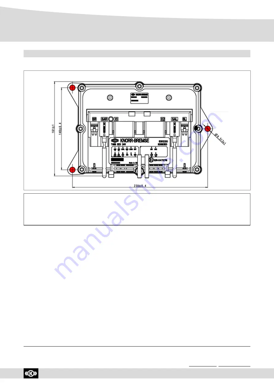
Diagram showing fixings for the KB4TA D ECU (view without Cover)
Notes:
Tightening torque of the M8 retaining nuts/screws = 24 +/- 4.8 Nm.
The ECU should be mounted on a flat surface. The cable entries must not point upwards.
The pressure compensation hole on the back must not be blocked.
1) Fit the KB4TA D ECU to the trailer either:
- on a cross member in the centre of the rear axle bogie
or
- on the trailer headboard.
If required fit the additional axle modulator, normally on a cross member in the centre of the front axle bogie.
2) Make the necessary pneumatic connections between the pneumatic components.
3) Make the necessary electrical connections - see PD-203-380, Document No.
Y250909.
Required checks after installation
1) Before performing the checks, chock the wheels.
2) Fully charge air brake system and verify proper brake adjustment.
3) Make several trailer brake applications and check for prompt application and release at each wheel brake.
4) Check the module, modulator valve(s) and all air hose fittings for leakage using a soap solution.
5) Apply power and monitor the power-up sequence to verify proper system operation.
6) Determine the current ABS configuration by activating blink code diagnostics or using the PC diagnostic tool
ECU
talk
®
(see PD-203-390, Document No.
Y250910
).
7) Where necessary configure the required ABS configuration and Auxiliary configuration using the diagnostic tool
ECU
talk
®
.
8) It is recommended that a full EOL check is carried out using the diagnostic tool ECU
talk
®
.
Y026787: 006: EN: Released: Fri Nov 11 11:18:50 CET 2016:


