10
Knorr-Bremse Group
PD-203-360
Doc. No. Y250908 (EN - Rev. 001)
September 2016
The information contained herein is subject to alteration without notice and therefore may not be the latest release. Please check our website www.knorr-bremseCVS.com for the latest update or contact your local Knorr-Bremse representative.
The figurative mark “K” and the trademarks KNORR and KNORR-BREMSE are registered in the name of Knorr-Bremse AG. Additional terms and conditions apply; please refer to our website knorr-bremseCVS.com for full Disclaimer.
Note: If service work is carried out on a vehicle based on information provided herein, it is the responsibility of the workshop to ensure the vehicle is fully tested and in full
functional order before the vehicle is returned into service. Knorr-Bremse accepts no liability for problems caused as a result of appropriate tests not being carried out.
Copyright © Knorr-Bremse AG - all rights reserved, including industrial property rights applications. Knorr-Bremse AG retains any power of disposal, such as for copying and transferring.
Knorr-Bremse Systeme für Nutzfahrzeuge GmbH . Moosacher Straße 80 . 80809 Munich . Germany . Tel: +49 89 3547-0 . Fax: +49 89 3547-2767 . www.knorr-bremse.com . www.knorr-bremseCVS.com
KB4TA/KB4TA D System Components
P r o d u c t D a t a
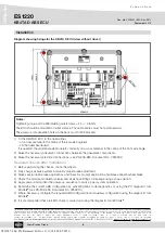
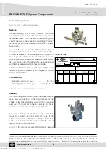
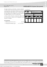
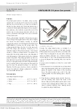
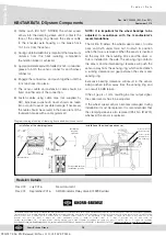
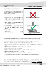
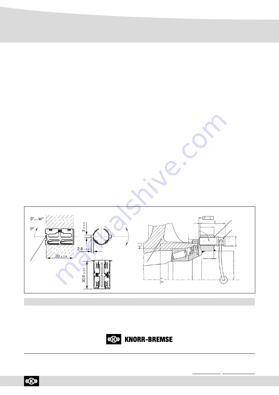
Diagram showing mounting of clamping sleeve and wheel speed sensor
Installation of the clamping sleeve
Pressed in fully
Permissible vertical
installation position
Installation
position
optional
Installation of the wheel speed sensor
3
+2
54
0.2 A
>3.5
0.6
±0.2
x45°
A
Ø18
H11
Ø21
30
±0.4
90
± 2.5
Sleeve pressed in
against the stop
Sensor carefully
inserted (do not
use a hammer!)
Rev. 000
July 2016
New document.
Rev. 001
September 2016
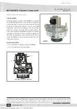
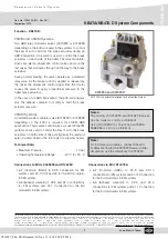
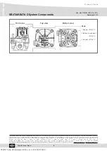
ABS Modulator Relay Valve K019299 added.
3) Gently push (DO NOT STRIKE) the wheel speed
sensor into the clamping sleeve until it contacts the
face of the sensing ring. Secure the sensor cable
to the knuckle/ axle housing or the brake hose
10-15 cm from the sensor.
4) During cable installation it is important that maximum
distance from the heat radiating components
(foundation brake) is achieved.
5) Apply a moderate amount of dielectric non-conductive
grease to both the sensor connector and harness
connector.
6) Engage the connectors, and push together until the
lock tab snaps into place.
7) The sensor cable and extension cable should be
fixed on either side of the connection.
8) Fasten cables using cable clips (not supplied by
KB), individual suspension travel should be taken
into account to avoid possible damage. If necessary
the cable should be secured in the back plate of the
foundation brake with a cable grommet!
NOTE: It is important for the wheel bearings to be
adjusted in accordance with the manufacturer’s
recommendations.
The friction fit allows the wheel speed sensor to slide
back and forth under force but to retain its position
when the force is removed. When the sensor is inserted
all the way into the mounting block and the drum or
hub is installed on the axle, the sensing ring contacts
the sensor and normal bearing clearance will push the
sensor away from the sensing ring, which will establish
a running clearance (air gap) between the sensor and
sensing ring.
Excessive bearing clearance will result in the sensor
being pushed further away from the sensing ring and
can result in ABS failure.
If the air gap is >1 mm, resulting in a low output signal,
the speed sensor has to be adjusted.
If the wheel speed sensor becomes damaged during
installation it must be replaced. It is recommended that
the clamping sleeve is also replaced (Part No.
II
16774)
whenever the sensor is replaced.
Revision Details
Y026787: 006: EN: Released: Fri Nov 11 11:18:50 CET 2016:

