3
Knorr-Bremse Group
PD-203-380
Doc. No. Y250909 (EN - Rev. 000)
July 2016
The information contained herein is subject to alteration without notice and therefore may not be the latest release. Please check our website www.knorr-bremseCVS.com for the latest update or contact your local Knorr-Bremse representative.
The figurative mark “K” and the trademarks KNORR and KNORR-BREMSE are registered in the name of Knorr-Bremse AG. Additional terms and conditions apply; please refer to our website knorr-bremseCVS.com for full Disclaimer.
Note: If service work is carried out on a vehicle based on information provided herein, it is the responsibility of the workshop to ensure the vehicle is fully tested and in full
functional order before the vehicle is returned into service. Knorr-Bremse accepts no liability for problems caused as a result of appropriate tests not being carried out.
Copyright © Knorr-Bremse AG - all rights reserved, including industrial property rights applications. Knorr-Bremse AG retains any power of disposal, such as for copying and transferring.
Knorr-Bremse Systeme für Nutzfahrzeuge GmbH . Moosacher Straße 80 . 80809 Munich . Germany . Tel: +49 89 3547-0 . Fax: +49 89 3547-2767 . www.knorr-bremse.com . www.knorr-bremseCVS.com
C o m m e r c i a l V e h i c l e S y s t e m s
Cables for KB4TA/KB4TA D
Installation of wheel speed sensor extension
cables and modulator connection cables
The rotation angle of the fifth wheel and the suspension
travel must be taken into account when determining cable
length and also during installation.
To reduce the risk of damage and subsequent faults in the
system, Knorr-Bremse recommends the following:
1) Lay the modulator cable and the wheel speed sensor
cables separately on the vehicle frame. The sensor
cable should have a minimum distance to other cables
of approximately 5 –10 cm.
2) Cables installed in conduit must be protected at entry
and exit with cable grommets.
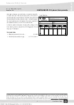
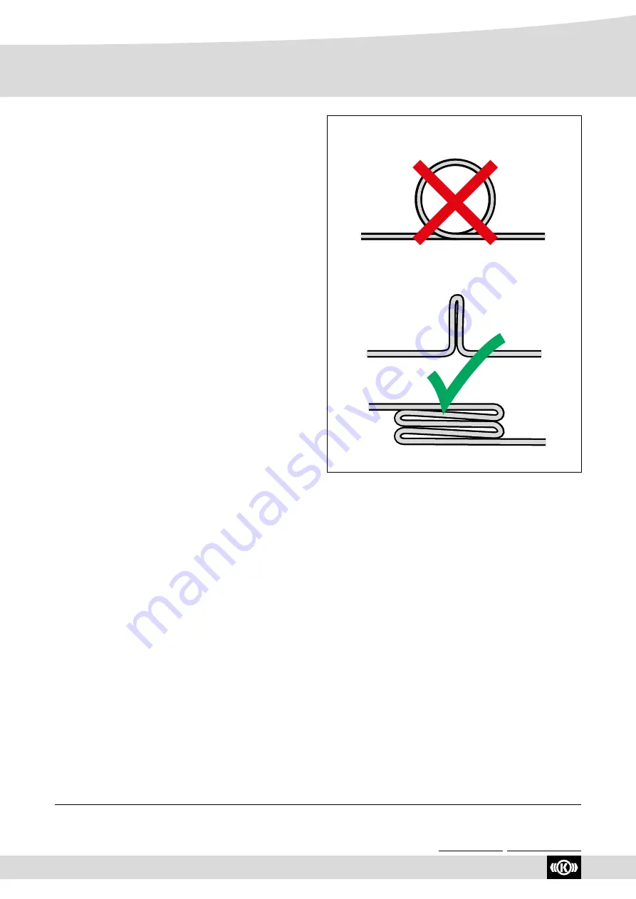
3) It is
not permitted
to ‘lose’ any excessive length of the
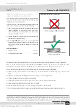
extension and connection cables in circular loops or ring
form. Excess cable should be detoured or folded (see
diagram).
Wire cross section
• Modulator cable: . . . . . . . . . . . . 1.0 mm²
• Wheel speed sensor cable: . . . . . . . 0.75 mm²
Circular looping is
not
permissible
Permissible methods
Installation of excess cable length
All cables are environmentally sealed at the connector interface and are clearly labelled for correct installation.
Because of the moulded design of the KB4TA module/KB4TA D ECU wiring harnesses and individual cables,
Knorr-Bremse recommends that a complete harness or cable be replaced if damage or corrosion occurs.
When troubleshooting ABS wiring, some general rules should be followed where applicable:
1) Check all wiring and connectors to ensure they are secure and free from visible damage (e.g. cuts, abrasions,
etc.).
2) Check for evidence of wire chafing due to poor routing, or poor securing of wires.
3) Check connectors for proper insertion and locking.
4) Connector terminals must not show signs of corrosion or exposure to the environment.
5) Never pierce wire insulation when checking for continuity.
6) Do not deform individual pins or sockets during probing with a volt/ohm meter.
7) It is strongly recommended to properly secure all wiring harness and sensor leads at least every 45 cm.
Y026787: 006: EN: Released: Fri Nov 11 11:18:50 CET 2016:

