Knorr-Bremse Group
3
Doc. No. Y250910 (EN - Rev. 001)
September 2016
The information contained herein is subject to alteration without notice and therefore may not be the latest release. Please check our website www.knorr-bremseCVS.com for the latest update or contact your local Knorr-Bremse representative.
The figurative mark “K” and the trademarks KNORR and KNORR-BREMSE are registered in the name of Knorr-Bremse AG. Additional terms and conditions apply; please refer to our website knorr-bremseCVS.com for full Disclaimer.
Note: If service work is carried out on a vehicle based on information provided herein, it is the responsibility of the workshop to ensure the vehicle is fully tested and in full
functional order before the vehicle is returned into service. Knorr-Bremse accepts no liability for problems caused as a result of appropriate tests not being carried out.
Copyright © Knorr-Bremse AG - all rights reserved, including industrial property rights applications. Knorr-Bremse AG retains any power of disposal, such as for copying and transferring..
Knorr-Bremse Systeme für Nutzfahrzeuge GmbH . Moosacher Straße 80 . 80809 Munich . Germany . Tel: +49 89 3547-0 . Fax: +49 89 3547-2767 . www.knorr-bremse.com . www.knorr-bremseCVS.com
KB4TA / KB4TA D System Diagnostics
C o m m e r c i a l V e h i c l e S y s t e m s
PD-203-390
Blink Code Diagnostics
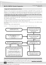
The KB4TA module/KB4TA D ECU provides diagnostic and configuration functions through blink code diagnostics.
This means that the technician, even without diagnostic tools, can read a series of blinks of the ABS warning lamp(s)
(in the cab of the towing vehicle and/or on the trailer headboard) to diagnose the trouble codes being generated.
However to enter this diagnostic mode the KB4TA module/KB4TA D ECU must be wired to accept both a permanent
and stop lamp power supply.
The blink code diagnostics mode is entered by providing constant power to the ignition circuit and by switching the
stop lamp power input supply “ON” and “OFF” a number of times (see Diagnostic Trouble Codes). With a parked
towing vehicle attached to the trailer, this is achieved by switching on the ignition and, after the power up sequence is
complete, applying and releasing the brake pedal a number of times (see Diagnostic Trouble Codes). Depending on
the blink code mode activated, the KB4TA module/KB4TA D ECU will blink the trailer ABS warning lamp(s) to display:
–
active faults
–
inactive faults (fault history)
–
ABS configuration
–
odometer mileage.
Wait until after the modulator ‘chuff test’ before activating the stop lamp power. Following a single display of all
available messages, the trailer ABS warning lamp(s) will remain on for five seconds and then return to normal
operating mode.
Blink code diagnostics can only be activated following a power up, where wheel speeds have not been detected.
If a wheel speed signal is generated during the blink code diagnostics mode, the module will cancel the blink code
diagnostics and return to normal operating mode. Blink code diagnostics must be activated within the first 15
seconds of ignition power being applied.
If stop lamp power is continuously applied for longer than five seconds, blink code diagnostics will be disabled until
the next time the ignition power is cycled.
Diagnostic Trouble Codes (DTCs)
Display “Active” DTCs
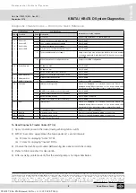
To display “active” codes, switch on the ignition and apply/release the brake pedal three times within 15 seconds.
Following activation, there will be a five second delay followed by a blink code display of all “active” trouble codes.
Display “Inactive” DTCs
To display “inactive” trouble code history, switch on the ignition and apply/release the brake pedal four times within
15 seconds. Following activation, there will be a five second delay followed by a blink code display of all “inactive”
trouble codes held in the ECU memory.
Y026787: 006: EN: Released: Fri Nov 11 11:18:50 CET 2016:

