Knorr-Bremse Group
5
Doc. No. Y250910 (EN - Rev. 001)
September 2016
The information contained herein is subject to alteration without notice and therefore may not be the latest release. Please check our website www.knorr-bremseCVS.com for the latest update or contact your local Knorr-Bremse representative.
The figurative mark “K” and the trademarks KNORR and KNORR-BREMSE are registered in the name of Knorr-Bremse AG. Additional terms and conditions apply; please refer to our website knorr-bremseCVS.com for full Disclaimer.
Note: If service work is carried out on a vehicle based on information provided herein, it is the responsibility of the workshop to ensure the vehicle is fully tested and in full
functional order before the vehicle is returned into service. Knorr-Bremse accepts no liability for problems caused as a result of appropriate tests not being carried out.
Copyright © Knorr-Bremse AG - all rights reserved, including industrial property rights applications. Knorr-Bremse AG retains any power of disposal, such as for copying and transferring..
Knorr-Bremse Systeme für Nutzfahrzeuge GmbH . Moosacher Straße 80 . 80809 Munich . Germany . Tel: +49 89 3547-0 . Fax: +49 89 3547-2767 . www.knorr-bremse.com . www.knorr-bremseCVS.com
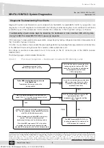
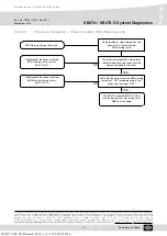
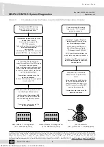
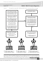
KB4TA / KB4TA D System Diagnostics
C o m m e r c i a l V e h i c l e S y s t e m s
PD-203-390
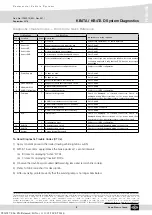
Diagnostic Trouble Codes — Blink Code Quick Reference
1st Blink Code
2nd Blink Code
Information on action required
Code
Location
Code
Description
1
All
1
No Faults
System fully operational - no faults detected
2
3
4
5
Sensor SL
Sensor SR
Sensor SAL
Sensor SAR
1
Wheel speed sensor air gap is too big
Go to Chart 5
2
Loss of wheel speed sensor signal
Go to Chart 5
3
Noisy wheel speed sensor signal
Go to Chart 5
4
Short or open circuit wheel speed sensor
Go to Chart 5
5
Tyre size differential out of range
Verify correct tyre size, proper tyre inflation & correct number
of sensing ring teeth. Verify that the ECU has the correct tyre
size settings.
6
Wheel speed sensor configuration error
Verify correct ABS configuration.
6
Power Supply
1
Voltage too high
Go to Chart 4
2
Voltage too low
Go to Chart 4
3
Excessive resistance ISO 7638 pin 1
Go to Chart 4
7
8
9
Modulator M22
Modulator M21
AUXIO1 / Modulator
2
Exhaust solenoid shorted or open circuit
Go to Chart 6
3
ABS valve installation error
Go to Chart 6
4
Valve configuration error
Verify correct ABS configuration.
10
Common
1
Internal short to ground
Check for damaged or corroded connectors. Check for
damaged wiring. After corrections or if no issues found, then
clear trouble codes. If problems return, replace the module.
2
AUXIO1 or modulator 2 short to ground
Go to Chart 6
3
ABS modulator dynamic error - all valves
Go to Chart 6
4
Excessive ABS activity
Go to Chart 4 or Chart 6
5
AUXIO1 or modulator 2 short to battery
Go to Chart 6
11
ECU
1
Internal error
Check for damaged or corroded connectors. Check for
damaged wiring. After corrections or if no issues found, then
clear trouble codes. If problems return, replace the module.
2
Configuration error
Verify correct ABS configuration.
12
AUXIO2
1
Shorted or open circuit
Check for corroded/damaged wiring or connectors
13
AUXIO3
1
Shorted or open circuit
Check for corroded/damaged wiring or connectors
14
System
2
Service Interval Exceeded
...
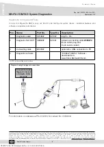
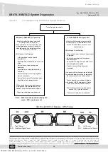
To Read Diagnostic Trouble Codes (DTCs):
1) Apply constant power to the trailer (towing vehicle ignition switch).
2) Within 15 seconds, apply/release the brake pedal at 1 second intervals:
(a) 3 times for displaying “Active” DTCs.
(b) 4 times for displaying “Inactive” DTCs.
3) Observe the dashboard mounted ABS warning lamp and record blink code(s).
4) Refer to blink code chart for description.
5) After resolving problems, verify that the warning lamp is no longer illuminated.
Y026787: 006: EN: Released: Fri Nov 11 11:18:50 CET 2016:

