8
Knorr-Bremse Group
The information contained herein is subject to alteration without notice and therefore may not be the latest release. Please check our website www.knorr-bremseCVS.com for the latest update or contact your local Knorr-Bremse representative.
The figurative mark “K” and the trademarks KNORR and KNORR-BREMSE are registered in the name of Knorr-Bremse AG. Additional terms and conditions apply; please refer to our website knorr-bremseCVS.com for full Disclaimer.
Note: If service work is carried out on a vehicle based on information provided herein, it is the responsibility of the workshop to ensure the vehicle is fully tested and in full
functional order before the vehicle is returned into service. Knorr-Bremse accepts no liability for problems caused as a result of appropriate tests not being carried out.
Copyright © Knorr-Bremse AG - all rights reserved, including industrial property rights applications. Knorr-Bremse AG retains any power of disposal, such as for copying and transferring..
Knorr-Bremse Systeme für Nutzfahrzeuge GmbH . Moosacher Straße 80 . 80809 Munich . Germany . Tel: +49 89 3547-0 . Fax: +49 89 3547-2767 . www.knorr-bremse.com . www.knorr-bremseCVS.com
Doc. No. Y250910 (EN - Rev. 001)
September 2016
KB4TA / KB4TA D System Diagnostics
P r o d u c t D a t a
PD-203-390
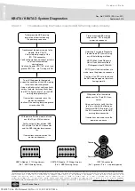
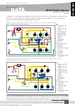
Chart 3
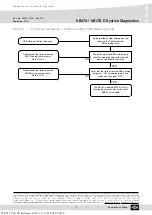
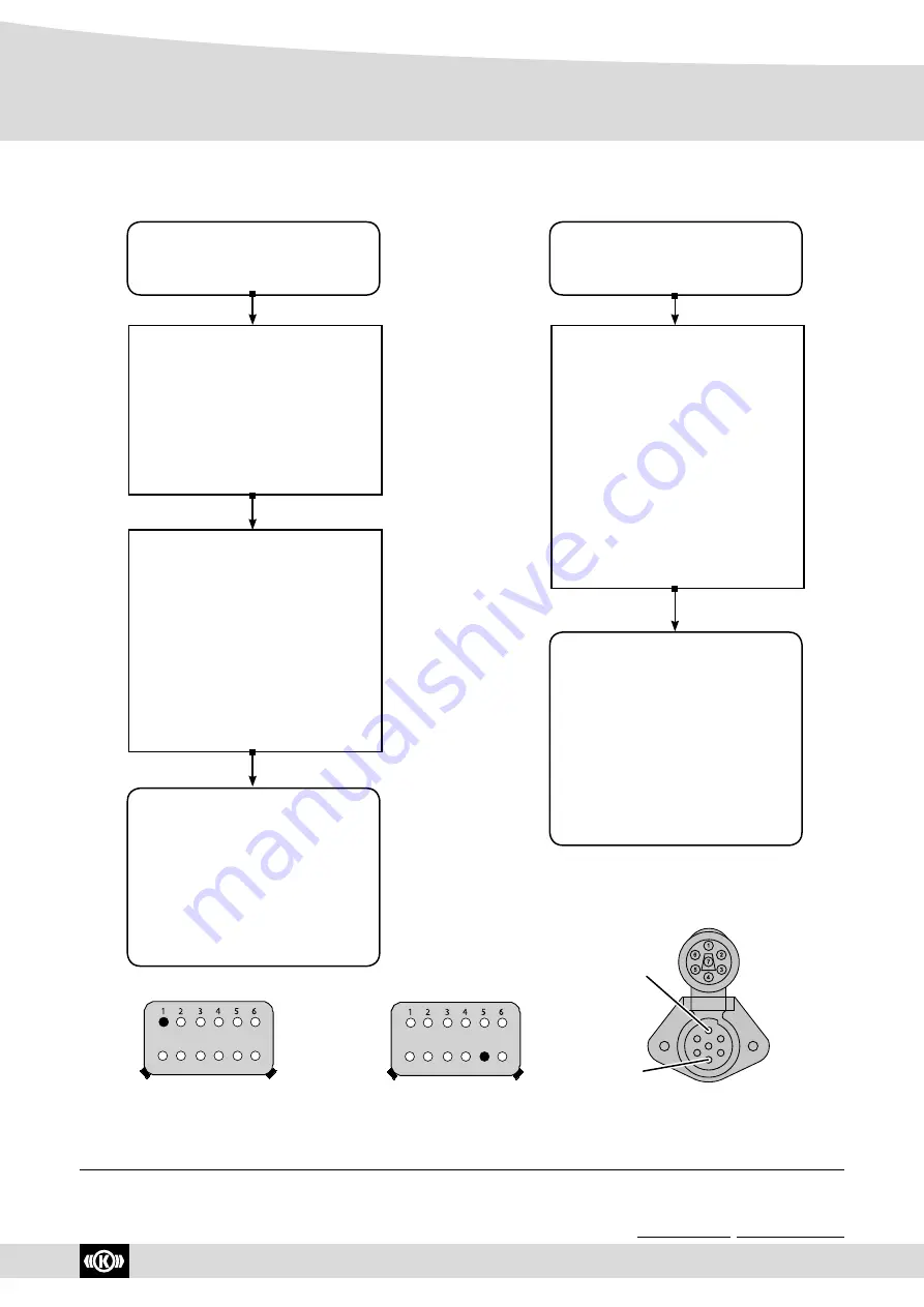
Troubleshooting the Trailer-mounted ABS Warning Lamp Circuitry
KB4TA Module - X1 Wiring Harness
(Pin 1 - ABS Warning Lamp)
ISO1185-connector
(Pin 1 - ground / Pin 4 - stop lamp power)
12 11 10
9
8
7
Ground
Power
Trailer-mounted ABS warning
lamp did not illuminate during
the power-up sequence.
Troubleshoot the power supply to the
module.
Go to Chart 4.
Verify stop lamp supply at the
ISO 1185 connector.
Verify configuration and correct installati-
on of the trailer-mounted
warning lamp.
Continue if power (ISO1185 - pin 4) and
ground (ISO1185 - pin 1) wiring are OK.
Turn off the power to the module.
Inspect the condition of the ABS warning
lamp, connector and ground.
Using a volt/ohm meter, verify continuity
across the bulb. Verify continuity from
the ISO 1185 ground (pin 1) to the ABS
warning lamp ground pin.
If corrections are made, rerun the
power-up sequence.
Continue if the warning lamp and ground
wire check out OK.
With power off to the module, discon-
nect the 12-pin ECU connector.
Verify continuity from external ABS
WL pin (pin 1) of the ECU connector
and the ABS indicator lamp connec-
tor.
If corrections are made, rerun the
power-up sequence.
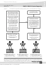
Trailer-mounted ABS warning
lamp remains “ON” during the
power-up sequence.
Determine if a module Diagnostic
Trouble Code (DTC) exists using
any of the following methods:
- KB4TA Blink Code Diagnostic.
Got to Quick Reference table.
- PC-diagnostic tool ECU
talk
®
If DTC(s) exist and corrections are
made, rerun the power-up sequence.
Continue if no DTCs are found and
the ABS module appears to be func-
tioning normally.
With power off to the module,
disconnect the 12-pin ECU con-
nector.
Using a volt meter, verify that the-
re is no a short to Vbat between
the external ABS WL pin (pin 1) of
the ECU connector and the ABS
warning lamp connector.
If corrections are made, rerun the
power-up sequence.
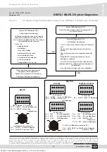
KB4TA D Module - X1 Wiring Harness
(Pin 8 - ABS Warning Lamp)
12 11 10
9
8
7
Y026787: 006: EN: Released: Fri Nov 11 11:18:50 CET 2016:

