TEMON 4-C
Doc. N°
MO-0368-ING
Microener. - Copyright 2010
2.1
Date
01.12.2008
Rev.
0
Pag.
9
of
14
9.7 - Selection of the alarm and tripped threshold
The set phase of the alarm thresholds start from the programming for the measure channel number 1.
The ALARM led on indicates the programming of the alarm threshold:
With
and
keys to select the value of temperature
Interval of programming from 5°C up to the tripping threshold -1°C
Confirm with ENTER.
The TRIP led on indicates the programming phase of the tripping threshold.
With
and
keys to select the value of temperature
Interval of programming from alarm thr 1°C up to 200°C.
Confirm with ENTER.
Repeat the same operation for the measure channels successive.
9.8 -
Selection of address network identification for the communication of the serial port
(MODBUS-RTU protocol)
NOTE: This set haven’t mean for the models without the
serial output
RS485 option installed.
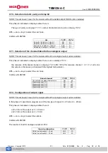
This phase is indicated on displays where there is
value in definition on displays T1-T2, ID on displays T3-T4
With
and
keys to select the number choice.
The range for value accepted is from 1 to 247.
Confirm with ENTER.
9.9 - Selection of baud rate
NOTE: This set haven’t mean for the models without the
serial output
RS485 option installed.
This phase is indicated on displays where there is
BDR on displays T1-T2, and the value to set on displays T3-T4.
With
and
keys to select the baud rate choice.
It’ possible to set the following values: 2,4 - 4,8 - 9,6 - 19,2 kbps.
Confirm with ENTER.
Set
T1-T2
T3-T4
Set address network
1
ID
Set
T1-T2
T3-T4
Baud rate: 19200
BDR
19.2
Baud rate: 9600
BDR
9.6
Baud rate: 4800
BDR
4.8
Baud rate: 2400
BDR
2.4


