15
3
Service Instructions
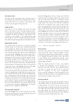
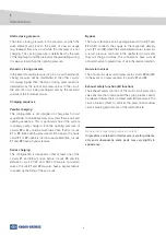
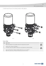
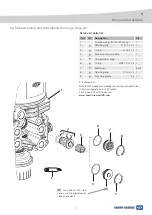
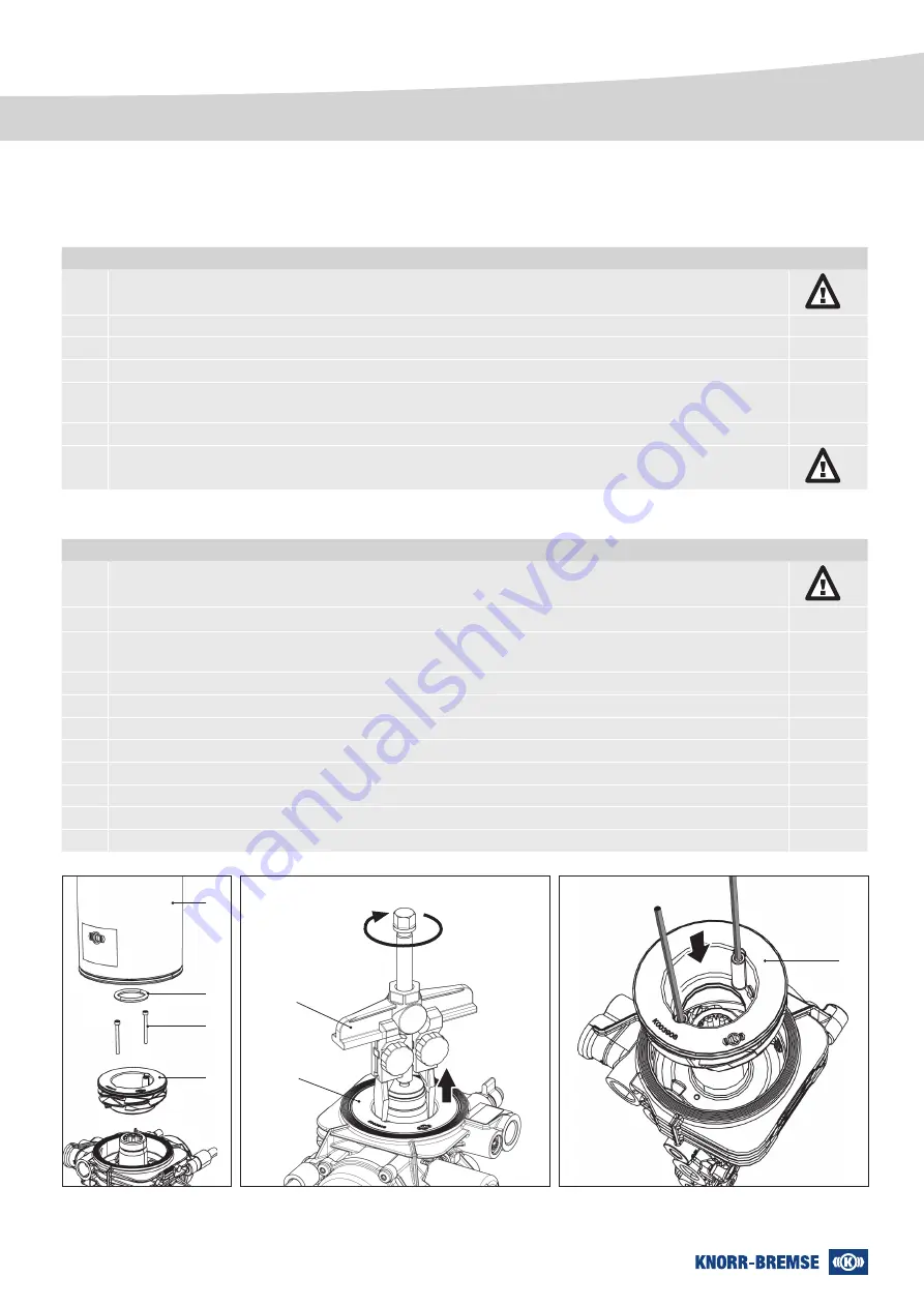
Fig. 2
Fig. 3
Fig. 4
Fitting the oil separator
Step
Service task
1
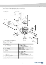
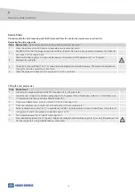
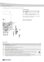
Check that the sealing surfaces of the oil separator unit (1) and the cartridge neck (not shown) are clean. Fit the
new O-rings (2 and 3) (Fig. 1 on Page 15) and lightly grease them.
2
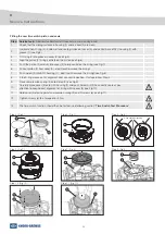
Put 2 rods (Ø 2.5 mm) (Fig. 4) into the threads for screws (4) to guide the oil separator into the body (Fig. 4).
3
Place the new oil separator unit (1) or cleaned original unit (dependent on kit purchased) into the body. Push the
unit down until it is correctly seated.
4
Fit and tighten screws (4) to a torque of 2.5 Nm.
5
Lightly lubricate the gasket at the base of the cartridge (6) with grease.
6
Lubricate new O-ring (5) with grease.
7
Fit O-ring (5) over the cartridge retaining thread.
8
Screw desiccant cartridge (6) up to stop.
9
Fully tighten desiccant cartridge (6) by turning a further ½ turn using a suitable strap wrench.
10
Refit (if necessary) the air processing unit to vehicle and check according to chapter 3.10.
11
Charge the air system to just below cut-out pressure and check the desiccant cartridge for leakage.
Removing the oil separator
Step
Service task
1
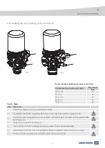
Clean the outside of the air processing unit and its surroundings to prevent entry of dirt.
2
Secure the ZB44.. either to a simple fixture or using the mounting bolts/studs to make it stable.
3
Unscrew desiccant cartridge (6) counter-clockwise, using suitable strap wrench.
4
Remove the screws (4) and O-ring (5).
5
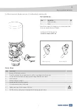
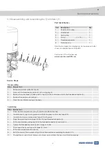
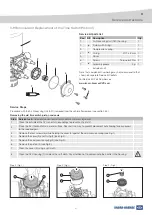
Fit a suitable pulling tool (7) into oil separator unit (Fig. 3). For detailed specification and correct fitting of
recommended tool see page 16.
6
Pull out the oil separator unit (1) by using of pulling tool (7).
7
If the oil separator unit (1) is not being replaced (depending on kit purchased), clean the the original unit (1) with
water using a high pressure hose or alternatively with gasoline. Also clean the housing using a soft cloth.
Service Steps
1
4
5
6
1
1
7


