3
1
2
4
5
6
19
3
Service Instructions
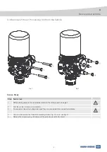
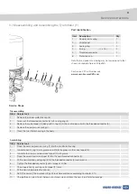
Disassembling
Step
Service task
1
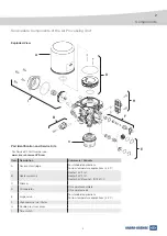
Remove the rubber protective cap (6).
2
Screw-out the threaded connector (5) with sealing ring (3).
3
Remove the valve tappet (2) (along with O-ring (4)) if it has not come out with the threaded connector (5).
4
Remove the compression spring (1).
5
Clean the tyre inflator housing in the body.
Assembling
Step
Service task
1
Place the new compression spring (1) into the tyre inflator housing.
2
Lubricate new O-ring (4) with grease and fit into the groove in the valve tappet (2).
3
Lubricate the new assembled valve tappet (2) with grease.
4
Place the assembled valve tappet (2) into the new threaded connector (5).
5
Fit the new (metallic) sealing ring (3) to the threaded connector (5) and screw-in.
6
Tighten the threaded connector (5) to a torque of 50 Nm
7
Check operation by pushing valve tappet (2) twice.
8
Fit the new rubber protective cap (6) .
9
Refit (if necessary) the air processing unit to vehicle and check according to chapter 3.10.
10
Charge the air system to just below cut-out pressure and check the new tyre inflator for leakage.
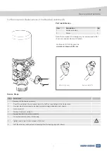
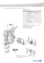
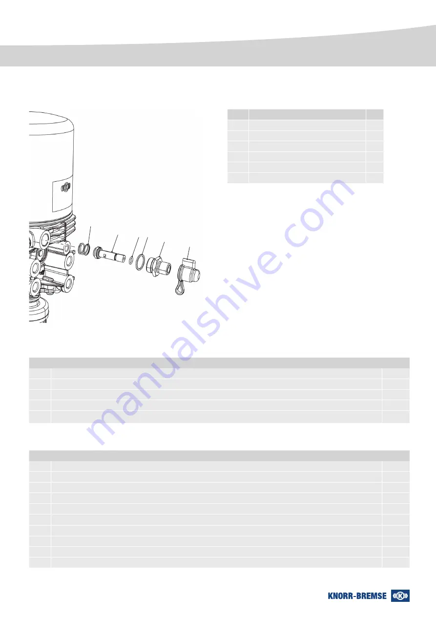
Item Description
Qty
1
Compression spring
1
2
Valve tappet
1
3
Sealing ring
1
4
O-ring
(7 x 1,5)
1
5
Threaded connector
1
6
Protective cap
1
Part Identification
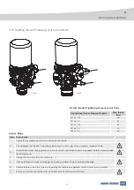
3 7 Disassembling and Assembling the Tyre Inflator (F)
Service Steps
For Service Kit Part Number see
www.knorr-bremseCVS.com
Note that component numbering may not correspond to that
shown on separate Service Kit leaflets.

