background image

KNOVA

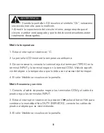
Medir el Diodo

1. Conecte el cable de prueba negro a las terminales COM y el cable de  
  prueba rojo a las terminales INPUT.

2. Sitúe el interruptor rotativo en       ; pulse el botón SEL para cambiar    
  a; conecte los cables de        prueba al objeto que se está midiendo 
  (conecte el cable de prueba rojo  al ánodo y el cable de prueba negro 
  al cátodo del diodo).

3. El valor Medido se visualiza en la pantalla.

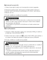
Prueba de Continuidad

1. Conecte el cable de prueba negro a las terminales COM y el cable de  
  prueba rojo a las terminales INPUT.

2. Sitúe el interruptor rotativo en       ; pulse el botón SEL para cambiar 
  a      ; conecte los cables de prueba al objeto que se está midiendo. 

3. Si la resistencia del circuito sometido a prueba es menor a 60, sonará   
  la alarma. 

  La alarma puede sonar o no si la resistencia del circuito a prueba se    

  encuentra entre los 60W y los 120W. La alarma no sonará si la    


  resistencia del circuito a prueba es mayor a 120W.

Medir la Capacitancia

1. Conecte el cable de prueba negro a las terminales COM y el cable de 
prueba rojo a las terminales INPUT.

2. Sitúe el interruptor rotativo en       ; pulse el botón SEL para cambiar a                
     ; conecte los cables de prueba al objeto que se está midiendo. 

3. El valor Medido se visualiza en la pantalla.

8

Summary of Contents for KN 8059

Page 1: ...KNOVA Digital clamp multimeter Multímetro digital de gancho 600V KN 8059 ...

Page 2: ... Safety Symbols 1 Warning 1 Maintenance 2 Introduction 3 Description 3 Panel Description 5 Operation 6 Accuracy Specification 10 General Specifications 13 Auto power off 13 Replace battery 14 Accessory 14 TABLE OF CONTENTS ...

Page 3: ...l from Hazardous Live conductors is permitted Double insulated Protection class II Earth ground To avoid possible electric shock personal injury or death read the following before using the Meter Use the test leads supplied to ensure operation safety If required they must be replaced with test leads of the same model or class Inspect the test leads before use Do not use them if insulation is dam a...

Page 4: ...nge functions Disconnect circuit power and discharge all high voltage capacitors before testing resistance continuity diodes or capacitor Do not store or use the meter in areas exposed to direct sunlight at high temperature or with high relative humidity Do not touch live circuit or exposed metal MAINTENANCE Before opening the rear of the meter disconnect test leads from all sources of electric cu...

Page 5: ... Jaws Designed to pick up the AC current flowing through the conductor 2 Hand Guards To protect user s hand from touching the dangerous area 3 Rotary Switch Select proper Range and function 4 HOLD button Pressing the hold button the meter stops updating the LCD panel LCD display press the button again and the meter exits hold mode 5 RAN auto manual Range button In Voltage resistance measurement mo...

Page 6: ... function from voltage frequency to duty 10 SEL Function selecting button In voltage mode press the SEL button to toggle from DCV to ACV in mode it is used to select a function from resistance capaci tance diode to continuity 11 Back light Press the button more than two seconds to turn on the back light press again to turn it off 12 Trigger Press the lever to open the transformer jaws When the pre...

Page 7: ...KNOVA 1 2 3 4 5 6 8 9 10 11 12 13 7 PANEL DESCRIPTION 5 ...

Page 8: ... display Select the highest range if the value scale to be measured in the manual range is unknown To avoid harms to you or damages to the Meter from electric shock AC Voltage Measurement 1 Plug the black test lead into the COM terminals and the red test lead into the INPUT terminals 2 Set the rotary switch to V press SEL button switch to AC voltage connect the test leads to the object being measu...

Page 9: ... the Meter when measuring exposed conductor Measuring Resistance 1 Plug the black test lead into the COM terminals and the red test lead into the INPUT terminals 2 Set the rotary switch to press SEL button switch to Ω Connect the test leads to the object being measured 3 The measured value shows on the display At the manual range mode when only OL is shown on the LCD it means the measurement has e...

Page 10: ... INPUT terminals 2 Set the rotary switch to press SEL button switch to Connect the test leads to the object being measured 3 The buzzer sounds if the resistance of a circuit under test is less than 60 The buzzer may or may not sounds if the resistance of a circuit under test is between 60 Wto 120 W the buzzer does not sound if the resistance of a circuit under test is higher than 120W Measuring Ca...

Page 11: ... required plug thermocouple s K TYPE red terminal into INPUT terminal and black terminal into COM terminal measure object surface or around temperature with thermocouple s probe 4 The Measured value shows on the display Measuring frequency duty 1 Plug the black test lead into the COM terminals and the red test lead into the INPUT terminals 2 Set the rotary switch to V press Hz button switch to Hz ...

Page 12: ...cient 0 1x specified accuracy 1 center the conductor within the transformer jaw otherwise it may cause 1 5 position error in AC current mode Conductor Mark Mark Mark Range Resolution Accuracy 400mV 0 1mV 4V 1mV 40V 10mV 400V 0 1V 600V 1V 1 0 reading 2 digits 0 8 reading 2 digits Input impedance 10MΩ Max input Voltage 600V DC or 600V AC Peak 10 ...

Page 13: ...digits 600V 1A 1 5 reading 5 digits 1 0 reading 10 digits 3 5 reading 20 digits 0 5A 3 0 reading 10 digits 5A 3 0 reading 10 digits 2 5 reading 10 digits Input impedance 10MΩ Frequency response 40Hz 400Hz Max input Voltage 600V DC or 600V AC Peak AC Voltage AC Current Frequency response 50Hz 60Hz Max Input Current Full Range 120 and measuring time less than 60 seconds 11 ...

Page 14: ...an about 60Ω will beep Open circuit voltage approximate 0 45V 1 2 reading 2 digits Overloading protection 600V DC or 600V AC peak Overloading protection 600V DC or 600V AC peak Resistance Diode Continuity The buzzer may or may not sounds if the resistance of a circuit under test is between 60 Ω to 120 Ω The buzzer does not sound if the resistance of a circuit under test is higher than 120Ω Overloa...

Page 15: ... 2 5 3 times Second Unit display Sign Polarity Display Overloading OL HOLD Display HOLD Low Battery indication Display Power supply DC1 5V X3 SIZE AAA battery Dimensions 208mm 78mm 35mm Weight 340g including Battery Max Jaw Size 26mm diameter Operating 5 C 35 C Storage 10 C 50 C Auto power off To preserve battery life the Meter automatically turns off if you do not turn the rotary switch or press ...

Page 16: ...and battery cover has been screwed before use Re place the battery as soon as the battery indicator appears Performs replace battery 1 Disconnect test leads from live circuit switch rotary switch to OFF position 2 Remove test leads form input terminals 3 Remove the screw from the battery cover and separate the battery compartment from the case bottom Replace the battery with 3pcs of new 1 5V AAA b...

Page 17: ...os de Seguridad 1 Advertencia 1 Mantenimiento 2 Introducción 3 Descripción 3 Descripción del Tablero 5 Operación 6 Especificaciones de Precisión 10 Especificaciones Generales 13 Apagado automático 13 Cambio de batería 14 Accesorios 14 INDICE ...

Page 18: ...ores vivos peligrosos Doble aislamiento Protección de clase II Descarga a tierra Para evitar posibles descargas eléctricas daños personales o muerte lea lo siguiente antes de utilizar el Multímetro Utilice los cables de prueba provistos para asegurar la seguridad de la operación De ser necesario deben reemplazarse por cables de prueba del mismo modelo o clase Revise los cables de prueba antes de u...

Page 19: ...odos los condensa dores de alto voltaje antes de probar la resistencia la continuidad los diodos o el condensador No almacene ni utilice el multímetro en áreas directamente expuestas a la luz solar altas temperaturas o con una humedad relativa alta No toque el circuito vivo ni el metal expuesto MANTENIMIENTO Antes de abrir la parte trasera del multímetro desconecte los cables de prueba de toda fue...

Page 20: ...A que fluye a través del conductor 2 Protecciones Para Manos To protect user s hand from touching the dangerous area 3 Interruptor Rotativo Selecciona la Escala y la función adecuadas 4 Botón HOLD RETENER Pulse el botón hold y el multímetro dejará de actualizar la pantalla LCD la pantalla LCD mostrará el símbolo pulse el botón nueva mente y el multímetro saldrá de la modalidad hold 5 RAN Botón de ...

Page 21: ...c cionar la función de voltaje frecuencia o servicio 10 SEL Botón de selección de función En la modalidad de voltaje presione el botón SEL para alternar entre CDV y CAV En la modalidad se utiliza para seleccionar una función de resistencia capacitancia diodo o continuidad 11 Luz de fondo Pulse el botón durante más de dos segundos para encender la luz de fondo Pulse nuevamente para apagarla 12 Gati...

Page 22: ...1 2 3 4 5 6 8 9 10 11 12 13 7 DESCRIPCIÓN DE TABLERO 5 ...

Page 23: ...más alta si se desconoce la escala de valores a medir en escala manual Evite daños a su persona o al Multímetro causados por una des carga eléctrica Medición de Voltaje CA 1 Conecte el cable de prueba negro a las terminales COM y el cable de prueba rojo a las terminales INPUT 2 Sitúe el interruptor rotativo en la posición V pulse el botón SEL para cambiar a voltaje CA conecte los cables de prueba ...

Page 24: ...r conductores expuestos Medir la Resistencia 1 Conecte el cable de prueba negro a las terminales COM y el cable de prueba rojo a las terminales INPUT 2 Sitúe el interruptor rotativo en pulse el botón SEL para cambiar a Ω conecte los cables de prueba al objeto que se está midiendo 3 El valor medido se visualiza en la pantalla En la modalidad de escala manual cuando sólo se visualice el símbolo OL e...

Page 25: ...ales INPUT 2 Sitúe el interruptor rotativo en pulse el botón SEL para cambiar a conecte los cables de prueba al objeto que se está midiendo 3 Si la resistencia del circuito sometido a prueba es menor a 60 sonará la alarma La alarma puede sonar o no si la resistencia del circuito a prueba se encuentra entre los 60W y los 120W La alarma no sonará si la resistencia del circuito a prueba es mayor a 12...

Page 26: ...conecte la terminal roja del termopar TIPO K en la terminal INPUT y la terminal negra en la terminal COM Mida la superfi cie del objeto o la temperatura que lo rodea con el sensor del termopar 4 El valor Medido se visualiza en la pantalla Medir frecuencia y servicio 1 Conecte el cable de prueba negro a las terminales COM y el cable de prueba rojo a las terminales INPUT 2 Sitúe el interruptor rotat...

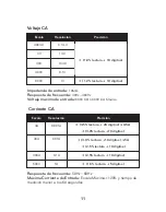
Page 27: ... Resolución Precisión 400mV 0 1mV 4V 1mV 40V 10mV 400V 0 1V 600V 1V 1 0 lectura 2 digitos 0 8 lectura 2 digitos Impedancia de entrada 10MΩ Voltaje máximo de entrada 600V DC or 600V AC Peak ESPECIFICACIONES DE PRECISIÓN Precisión a de lectura b dígitos garantizada por 1 año Temperatura de operación 18 28 Humedad Relativa 75 H R Coeficiente de temperatura 0 1x precisión específica 1 C 10 ...

Page 28: ... 5 digitos 1 0 lectura 10 digitos 3 5 lectura 20 digitos 0 5A 3 0 lectura 10 digitos 5A 3 0 lectura 10 digitos 2 5 lectura 10 digitos Impedancia de entrada 10MΩ Respuesta de frecuencia 40Hz 400Hz Voltaje máximo de entrada 600V CD ó 600V CA Máximo Voltaje CA Corriente CA Respuesta de frecuencia 50Hz 60Hz Máxima Corriente de Entrada Escala Máxima 120 y tiempo de medición menor a los 60 segundos 11 ...

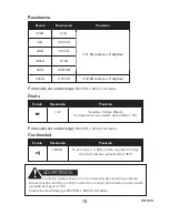
Page 29: ... menor a 60Ω emitirá un pitido Voltaje de circuito abierto aproximado 0 45V 1 2 lectura 2 digitos Protección de sobrecarga 600V CD ó 600V CA máximo Protección de sobrecarga 600V CD ó 600V CA máximo Resistencia Diodo Continuidad La alarma puede sonar o no si la resistencia del circuito a prueba se encuentra entre los 60 y los 120 La alarma no sonará si la resistencia del circuito a prueba es mayor ...

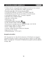
Page 30: ...unidad Símbolo Indicador de Polaridad Sobrecarga OL HOLD RETENER Indicador Aviso de batería baja Indicador Suministro de energía batería TAMAÑO AAA 1 5V CD X3 Dimensiones 208mm 78mm 35mm Peso 340g batería incluida Tamaño máximo de pinza 26mm de diámetro Operación 5 C 35 C Almacenamiento 10 C 50 C Apagado automático A fin de preservar la vida útil de la batería el Multímetro se apagará automáticame...

Page 31: ...ornillada antes de su uso Reemplace la batería ni bien aparezca el indicador Realizar el cambio de batería 1 Desconecte los cables de prueba del circuito vivo mueva el interruptor rotativo a la posición OFF 2 Retire los cables de prueba de las terminales de entrada 3 Retire el tornillo de la cubierta de de la batería y separe el compar timiento de la batería de la parte inferior de la carcasa Reem...

Page 32: ...www knova com mx ...

Reviews: