background image

ADDITIONAL SAFETY RULES FOR DUST COLLECTOR

SAFETY RULES FOR WORKING EQUIPMENT

  1. Read and become familiar with the entire operating

      manual.
  2. Keep guards and cover in place and working order.
  3. Always use safety glasses. Also use face or dusty.

      Everyday eye glasses only have impact resistant lenses,

      they are not safety glasses.
  4. Keep work area clean. Cluttered areas and benches

      invite accidents.
  5. Don’t

 force tool. It will do a better and safer job at the

      rate for which is was designed.
  6. Avoid accidental starting. Make sure switch is in “OFF”

      position before plugging in cord.
  7. Disconnect tools before servicing and when changing

      accessories such as blades, cutters.

  8. Don’t over reach. Keep your proper footing and balance 

      at times. For best footing wear rubber soled footwear.

      Keep floor clear of oil, scrap wood, etc.

  9. Wear

 proper apparel. Loose clothing or jewelry may

      get caught in moving parts. Wear protective hair

      covering to contain long hair.
10. Make workshop child proof. Place a padlock on the switch

      when blade saw is not in use and store the key in a safe 

      location.
11. Remove

 adjusting keys and wrenches. Form the habit 

      of checking to see that keys and adjusting wrenches

      are removed from tool before turning it on.

12. Avoid dangerous environment. Don’t use power tools in 

      damp or wet locations. Keep your work area well

      illuminated DO NOT USE in explosive atmosphere

      (around paint, flammable liquids, etc.)

13. Keep children away. All vistors should be kept a safe

      distance from work area, especially while operating unit.

14. Use the proper tool. Don’t force tool or attachment to

      do a job for which it was not designed.

15. Maintain tools in top condition. Keep tools sharp and 

      clean for best and  safest performance. Follow

      instructions for lubricating and changing accessories.
16. Secure

 your work. Use clamps or a vise to hold work,

      when practical. It’s safer than using your hand and

      prevents round or irregularly shaped pieces from turning.
17. Check

 damaged parts. Before further use of the tool, a 

      guard or other part that is damaged should be checked

      to assure that it will operate property and perform its

      intended function check alignment of moving parts,

      breakage of parts, mounting or any other conditions that 

      may affect its operations. A guard or other part that is

      damaged should be properly repaired or replaced.
18. Use recommended accessories. Consult owner’s manual.

      Use of improper accessories could be hazardous.
19. Never

 stand on tool. Injury could occur from a fall.

20. Never leave tool running and unattended.
21. Always remove cord plug from electrical outlet when

      adjusting, changing parts working on tool.

• Keep hair, loose clothing, fingers, and all parts of body away 

   from openings and moving parts.

• Extension

 cords in poor condition or that are too small can pose 

   fire and shock hazards. When using an extension cord, be sure 

   it is in good condition. See “Extension cords” in the

   “Operation” section for proper wire sizes.

• Connect to properly, grounded outlet only

   (See “Grounding instructions” on page 11)

Save these instructions

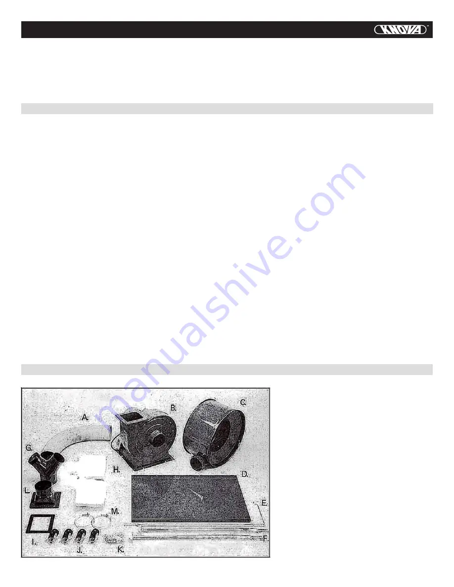
UNPACKING AND CHECKING CONTENTS

Unpack carton, check machine, to see parts listed below:

  A.  Hose
  B.  Collector body & Fan/Motor assembly
  C.  Collector body
  D.  Base plate
  E.  Upper bag support
  F.   Support
  G.  Inlet
  H.  Two bags
  I.  Packing
  J.  Four casters
  K.  Nuts, screws, washers, spring washers


and wrench

  L.  Outlet
  M.  Two hose clamp

2

Summary of Contents for KN CP-2042B

Page 1: ...KN CP 2042B Dust collector 2 Colector de polvo H P...

Page 2: ...as described in this manual To avoid personal injury or damage to dust collection system use only recommended accessories Sparks inside the electrical parts can ignite flammable vapors or dust To avo...

Page 3: ...chment to do a job for which it was not designed 15 Maintain tools in top condition Keep tools sharp and clean for best and safest performance Follow instructions for lubricating and changing accessor...

Page 4: ...wire Power wire SWITCH WIRING DIAGRAM Toggle switch 1 On Off switch 1 Red Black Groundig Green R T 3 Black Groundig Green S T Red R MOTOR CONTROL The dust collector switch is located on the left side...

Page 5: ...extension cords that have three prong grounding plugs and three pole receptacles that accept the tool s plug 6 Repair or replace damaged or worn card immediately 7 This machine is intended for use on...

Page 6: ...he wrench Fig 1 2 Position the collector body and fan motor assembly into place Secure it to the base plate using the nuts and washers provided as shown in figure 2 Fig 2 3 Next mount the outlet I to...

Page 7: ...C 6 The upper bag support should be attached to the collector support as shown in figure 7 Fig 7 Fig 8 a m 7 Now attach one end the hose a to the collector body and the other end to the side hole of t...

Page 8: ...shutter can now be placed on the intake hole of the fan motor assembly as shown in figure 13 Fig 12 Fig 13 12 Install the inlet shutter to the collector fan motor assembly using a 3 16 pan flange hea...

Page 9: ...damaged 1 Incorrect power wiring 2 Overloaded 1 Motor is dirty 2 Motor is damaged 1 Inlet port blocked 2 Lower bag is full 3 Flexible hose is broken 4 Hose clamp is too loose 1 Casters are damaged 2...

Page 10: ...9 EXPLODED DIAGRAM OF DUST COLLECTOR PARTS...

Page 11: ...wrench 10 MM x 12 MM 1 33 Wrench hex 5 MM 1 Specification Q ty Part No D e s c r i p t i o n 1 Caster 4 2 Screw hex flange head 5 16 18UNC x 1 2 32 4 Base plate 1 5 Screw pan flange head 10 24 UNC x...

Page 12: ...e gas natural hidr geno o polvos explosivos como el polvo de carb n polvo de magnesio polvo de grano o p lvora No aspire nada que se est quemando o que est humeando como cigarros cerillos o ceniza cal...

Page 13: ...ue son muy peque as pueden causar riesgos de fuego o choques el ctricos Cuando use un cable de extensi n aseg rese que est en buen estado Vea Cables de extensi n en la secci n Operaci n para los calib...

Page 14: ...DE CABLEADO DEL INTERRUPTOR Interruptor de palanca 1 Interruptor de botones 1 Rojo Negro A tierra Verde R T 3 Negro A tierra Verde S T Rojo R CONTROL DEL MOTOR El interruptor del colector de polvo est...

Page 15: ...s instrucciones de aterrizaje no son comprendidas en su totalidad o si existe la duda en cuanto a que la m quina est debidamente aterrizada 5 S lo se permite usar extensiones el ctricas que cuenten co...

Page 16: ...Coloque en ensamblaje de cuerpo de colector y ventilador en su lugar Aseg relo a la base usando las tuercas y roldanas provistas como se muestra en la Fig 2 Fig 2 3 A continuaci n monte la junta I y...

Page 17: ...El soporte superior de bolsa se debe unir al soporte de colector como se muestra en la Fig 7 Fig 7 Fig 8 a m 7 Ahora una un extremo de la manguera a al cuerpo del colector y el otro extremo al orifici...

Page 18: ...ll 12 Instale el divisor de entrada en el ensamblaje de ventilador motor usando un tornillo 3 16 Apriete con un destornillador como se muestra en la Fig 13 1 Fig 13 1 13 El colector de polvo ahora est...

Page 19: ...1 Cableado incorrecto del motor 2 Sobrecargado 1 El motor est sucio 2 El motor est da ado 1 Puerto de entrada bloqueado 2 La bolsa inferior est llena 3 La manguera est rota 4 Abrazadera de manguera mu...

Page 20: ...19 DIAGRAMA DE PARTES DEL COLECTOR DE POLVO...

Page 21: ...12 MM 1 31 Cable de correinte 1 32 Llave espa ola 10 MM x 12 MM 1 33 Llave hexagonal 5 MM 1 Especificaci n Cant Part No D e s c r i p c i n 1 Rueda 4 2 Tornillo 5 16 18UNC x 1 2 32 4 Placa base 1 5 To...

Page 22: ...www knova com mx...

Reviews: