background image

22.  USE  RECOMMENDED  SPEED  for  drill  accessory  and 

workpiece material. SEE INSTRUCTIONS that come with the 

accessory.
23. WHEN DRILLING large diameter holes, clamp the work-

piece firmly to the table. Otherwise, the bit may grab and spin 

the workpiece at high speed. DO NOT USE fly cutters or mul-

tiple-part hole cutters, as they can come apart or become un-

balanced in use.
24.  MAKE  SURE  the  spindle  has  come  to  a  complete  stop 

before touching the workpiece.

25. TO AVOID INJURY from accidental starting, always turn 

the switch OFF and unplug the drill press before installing or 

removing any accessory or attachment or making any adjust-

ment.
26. KEEP GUARDS IN PLACE and in working order.
27.  USE  ONLY  SELF-EJECTING  TYPE  CHUCK  KEY  as  pro-

vided with the drill press.

ELECTRICAL REQUIREMENTS AND SAFETY

3

IN  THE  EVENT  OF  A  MALFUNCTION  OR  BREAKDOWN,  

grounding provides a path of least resistance for electric cur-

rents and reduces the risk ofelectric shock. This tool is equipped 

with an electrical cord that has an equipment-grounding con-

ductor and a grounding plug. The plug must be plugged into a 

matching receptacle that is properly installed and grounded in 

accordance with all local codes and ordinances.

DO NOT MODIFY THE PLUG PROVIDED. If it will not fit the 

receptacle, have the proper receptacle installed by a qualified 

electrician.

IMPROPER  CONNECTION  of  the  equipment  grounding  con-

ductor can result in risk of electric shock. The conductor with 

the  green  insulation  (with  or  without  yellow  stripes)  is  the 

equipment  grounding  conductor.  If  repair  or  replacement  of 

the electrical cord or plug is necessary, DO NOT connect the 

equipment grounding conductor to a live terminal.

CHECK with a qualified electrician or service person if you do 

not completely understand the grounding instructions, or if you 

are not certain the tool is properly grounded.

USE  ONLY  THREE-WIRE  ExTENSION  CORDS  THAT  HAVE 

THREEPRONGED  GROUNDING  PLUGS  WITH  THREE-POLE 

RECEPTACLES THAT ACCEPT THE TOOL’S PLUG. REPAIR OR 

REPLACE DAMAGED OR WORN CORDS IMMEDIATELY.

GUIDELINES FOR ExTENSION CORDS

Make  sure  your  extension  cord  is  in  good  condition.  Use  an 

extension cord heavy enough to carry the current your product 

will  draw.  An  undersized  cord  will  cause  a  drop  in  line  volt-

age resulting in loss of power, overheating and burning out of 

the motor. The table on the right shows the correct size to use 

depending on cord length and nameplate ampere rating. If in 

doubt, use the next heavier gauge. The smaller the gauge num-

ber, the heavier the cord.

Be  sure  your  extension  cord  is  properly  wired  and  in  good 

condition. Always replace a damaged extension cord or have 

it repaired by a qualified person before using it. Protect exten-

sion cords from sharp objects, excessive heat and damp or wet 

areas.

Use a separate electrical circuit for your tools. This circuit must 

not be less than #12 wire and should be protected with a 15 

Amp time lag fuse. Before connecting the motor to the power 

line, make sure the switch is in the OFF position and electric 

current is rated the same as the current stamped on the motor 

nameplate. Running at a lower voltage will damage the motor.

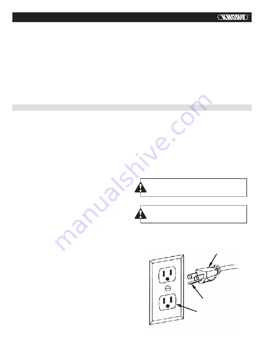
This drill press is intended for use on a circuit that has a re-

ceptacle like the one illustrated below. This shows a 3-prong 

electrical plug and receptacle that has a grounding conductor. 

The Canadian Electrical Code prohibits the use of adapters.

Fig. 1

Three-Pronged Plug

Grounding Prong

Properly Grounded

Three-Pronged Receptacle

CAUTION In all cases, make certain the receptacle 

is  properly  grounded.  If  you  are  not  sure,  have  a 

qualified electrician check the receptacle.

WARNING

This drill press is for indoor use only. Do not expose 

to rain or use in damp locations.

DRILL PRESS SAFETY 

Summary of Contents for KN DP-2000

Page 1: ...KN DP 2000 ...

Page 2: ...contain long hair TABLE OF CONTENTS 1 PROPOSITION 65 WARNING Some dust created by power sanding sawing grinding drilling and other construction activities contains chemicals known to the State of California to cause cancer birth defects or other reproductive harm Some examples of these chemicals are Lead based paints Crystalline silica from bricks cement and other masonry products Arsenic and chro...

Page 3: ...es excessively stop immediately turn the drill press off and unplug Do not restart until the problem is corrected 21 DO NOT perform lay out assembly or set up work on the table while the drill press is in operation DRILL PRESS SAFETY 2 10 WEAR A FACE MASK OR DUST MASK Drilling operation produces dust 11 DISCONNECT TOOLS before servicing when changing accessories such as blades bits cutters and the...

Page 4: ...d the grounding instructions or if you are not certain the tool is properly grounded USE only three wire extension cords that have threepronged grounding plugs with three pole receptacles that accept the tool s plug Repair or replace damaged or worn cords immediately GUIDELINES FOR EXTENSION CORDS Make sure your extension cord is in good condition Use an extension cord heavy enough to carry the cu...

Page 5: ...rench Hammer and block of wood Combination square Screwdrivers ELECTRICAL REQUIREMENTS AND SAFETY WARNING If any part is missing or damaged do not plug the drill press in until the missing or damaged part is replaced and assembly is complete Carefully unpack the drill press and all its parts and compare against the list below To protect the drill press from moisture a protective coating has been a...

Page 6: ...vei lock Base Support lock handle 5 CARTON CONTENTS Base Head motor assembly Table Chuck key Chuck Support lock handle Hex key 3 mm Bolts 3 Feed handles 3 KNOW YOUR DRILL PRESS Cover Spindle pulley Motor pulley Belt tension knob Chuck Table Column support Table support Column Feed handle Head lock screws ...

Page 7: ...ool used in the drill press to make holes in a workpiece DRILL ON OFF SWITCH Has locking feature This feature is intended to help prevent unauthorized and possible hazard ous use by children and others DRILLING SPEED Changed by placing the belt in any of the steps grooves in the pulleys See Spindle Speed inside belt guard FEED HANDLE Moves the chuck up or down One or two of the handles may be remo...

Page 8: ...dle surfaces with a clean cloth moistened with a non oil based solution such as Rubbing Alcohol 3 Open the chuck jaws 3 by turning the chuck barrel clock wise and make sure the jaws are completely recessed inside the chuck 4 Seat the chuck 1 Fig F onto the spindle by placing a block of wood under the chuck and tapping the wood with a hammer or tap the chuck with a rubber mallet or plastic tipped h...

Page 9: ...urning clockwise NOTE When the belts are new it may be difficult to move the belts As the machine is used the belts will gain more elastic ity and will be easier to adjust WARNING Disconnect the drill press from the power source be fore making any adjustments Fig H TO MOVE THE TABLE FIG I 1 Raise or lower the table 1 by loosening the support lock handle 2 2 Move the table to the desired position a...

Page 10: ... tension causes the quill to return too rapidly or too slowly 1 Lower the table for additional clearance 2 Place a screwdriver in the lower front notch 1 of the spring cap 2 Hold it in place while loosening and removing only the outer jam nut 3 3 With the screwdriver still engaged in the notch loosen the inner nut 4 just until the notch 5 disengages from the boss 6 on the drill press head Fig N 4 ...

Page 11: ...low 800 RPM 1260 RPM 1800 RPM 2400 RPM 3450 RPM See inside of the pulley guard for specific placement of the belts on the pulleys to change speeds WARNING To avoid possible injury keep guard closed in place and in proper working order while tool is in opera tion Fig Q Belt pulley position RPM chart BELT A 1 BELT B 2 BELT C 3 BELT D 4 BELT E 5 ON OFF SWITCH PANEL FIG R The ON OFF switch has a remov...

Page 12: ...EPTH Drilling a blind hole not all the way through workpiece to a given depth can be done two ways Workpiece method Fig U and V 1 Mark the depth 1 of the hole on the side of the workpiece 2 With the switch OFF bring the drill bit 2 down until the tip is even with the mark 3 Hold the feed handle at this position 4 Spin the lower nut 3 down to contact the depth stop lug 6 on the head 5 Spin the uppe...

Page 13: ...ed beneath work piece so that it contacts the left side of the column and a clamp to brace a small workpiece b Whenever possible position the workpiece to contact the left side of the column If it is too short or the table is tilted or clamp solidly to the table using the table slots c When using a drill press vice always fasten it to the table d Never do any work freehand hand holding the work pi...

Page 14: ...esult in personal injury Fig X WARNING The drill press vice MUST be clamped or bolted to the table to avoid injury from a spinning workpiece dam aged vice or bit parts HOLDING A DRILLING LOCATION 1 Using a centrepunch or sharp nail make an indentation in the workpiece where you want the hole 2 Using the feed handles bring the drill down to align with the indentation before turning the drill ON Fig...

Page 15: ...indle to remove all dirt grease and oil See ASSEMBLY INSTALLING THE CHUCK PROBLEM Noisy operation Drill bit burn Runout of drill bit point drilled hole not round Wood splinters on underside Workpiece torn loose from hand Drill bit binds in workpiece Excessive drill bit runout or wobble Quill returns too slow or too fast Chuck will not stay attached to spindle It falls off when trying to install Wa...

Page 16: ...asher Spindle Ball bearing C ring C ring 1 2 4 5 6 7 8 9 10 11 12 13 16 18 19 21 25 25 31 32 33 35 36 38 44 49 50 53 54 55 56 57 58 59 61 62 63 64 65 66 67 70 72A 74A 79 81 82 85 87 88 89 90A 92 99 101 112 113 131 149 160 151 150 162 164 165 167 169 500 601 602 604 700 10200131 10200202 10200407 2601BBDA90 10200603 2668BBDA27 2701FZD106 10200907 10201004 2701FZD111 10201202 2601QBDS81 10201602 265...

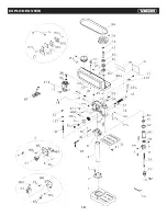
Page 17: ...EXPLODED VIEW 16 ...

Page 18: ...VESTIMENTA APROPIADA No utilice ropas ADVERTENCIA Algunos polvos generados por el lijado eléctrico el corte el molido el taladrado y otras actividades de la construcción contienen químicos que pueden causar cáncer defectos congénitos y otros daños reproductivos Algunos ejemplos de estos químicos son Pinturas a base de plomo Dióxido de silicio de ladrillos cemento y otros productos de albañilería A...

Page 19: ... sistemas de recolección de polvo cuando sea posible 23 SIEMPRE UTILICE PROTECCIÓN OCULAR Todo taladro de Prensa puede arrojar objetos extraños a los ojos que pueden causar daños permanentes SIEMPRE utilice gafas de seguridad no anteojos que cumplan con los estándares de seguridad ANSI Z87 1 los anteojos comunes sólo tienen lentes que re sisten impactos NO SON Gafas de seguridad NOTA Las Gafas que...

Page 20: ...toma corriente adecuado LA CONEXIÓN INDEBIDA del conductor a tierra del equipo puede resultar en riesgo de electrocución El conductor con recubrimiento aislante verde o con rallas amarillas es el con ductor de tierra del equipo Si repara o reemplaza el cable eléctrico o la clavija NO conecte el conductor a tierra del equipo a una terminal viva VERIFIQUE con un electricista calificado o personal de...

Page 21: ... Distancia total del cable en m Más de No más de 7 65 15 24 30 48 45 72 0 6 5 48 4 87 4 87 4 87 6 10 5 48 4 87 4 26 3 65 10 12 4 87 4 87 4 26 3 65 12 16 4 26 3 65 No recomendable CONTENIDO DE LA CAJA DESEMPACADO Y VERIFICACIÓN DE CONTENIDOS CUIDADO Si alguna parte no se encontrara o estuvieran dañadas no conecte el Taladro de Prensa hasta que la parte extraviada o dañada sea reemplazada y el ensam...

Page 22: ...nsamble del cabezal de motor Mesa Llave de broquero Broquero Manija de cerradura Llave allen 3 Cerrojos 3 Majas de alimentación 3 CONOZCA SU TALADRO DE PRENSA Cubierta Polea de huso Polea de motor Perilla de tensión de la banda Broquero Mesa Soporte de columna soporte de mesa Columna Manija de alimentación Tornillos de cerradura LISTA DE PARTES 21 Base Manija de cerradura Escala de Inclinación ...

Page 23: ... realizar agujeros en una pieza INTERRUPTOR DE ENCENDIDO APAGADO DEL TALADRO Posee un seguro Esta característica está diseñada para ayudar a prevenir el uso no autorizado y posiblemente pelig roso de niños y otras personas VELOCIDAD DE TALADRADO se cambia colocando la cor rea en cualquiera de los escalones surcos de las poleas Vea la velocidad del eje dentro del protector de correas MANIJA DE ALIM...

Page 24: ...es del mandril 3 girando el tambor del man dril en el sentido de las agujas del reloj y asegúrese de que los dientes estén completamente retraídas dentro del mandril 4 Asiente el mandril 1 Fig F en el eje ubicando un bloque de madera debajo del mandril y golpeando en la madera con un martillo o golpee el mandril con un martillo de goma 5 No golpee el mandril con un martillo de metal MONTAJE DEL TA...

Page 25: ...las correas para velocidades recomendadas de taladrado y posiciones de correa polea 5 Asegure las tuercas de tensión de la correa 2 haciéndolas girar en el sentido de las agujas del reloj NOTA Cuando las correas son nuevas puede ser difícil moverlas A medida que la máquina se utilice las correas ga narán elasticidad y serán más fáciles de ajustar CUIDADO Desconecte el taladro de prensa de la fuent...

Page 26: ...n la ranura afloje la tuerca interior 4 justo hasta que la ranura 5 se separe de la ranura principal 6 en la cabeza del taladro de presión Fig N 4 Cuidadosamente gire la cubierta de los resortes 2 en con tra de las agujas del reloj con un destornillador enganchando la próxima ranura 5 Baje la pluma a su posición inferior rotando la manija de alimentación en la dirección en contra de las agujas del...

Page 27: ...0 RPM 1800 RPM 2400 RPM 3450 RPM Ver dentro del recipiente de poleas para las ubicaciones es pecíficas de las correas en las poleas para cambiar las velo cidades CUIDADO Para evitar posibles heridas mantenga el receptáculo cerrado en su lugar y en funcionamiento apropiado mientras la herramienta se encuentra en operación Fig Q Banda carta de revoluciones por minuto de posición de polea Banda A 1 B...

Page 28: ...do de la pieza 2 Con el interruptor apagado baje la broca 2 hasta que la punta coincida con la marca 3 Sostenga la manija de alimentación en esta posición 4 Gire la tuerca inferior 3 hasta que haga contacto con el tope de profundidad 6 en la cabeza 5 Gire la tuerca superior 5 hacia abajo y no ajuste contra la tuerca inferior 3 6 Ahora la mecha se detendrá luego de recorrer la distancia marcada en ...

Page 29: ...ebajo de la pieza para que haga contacto con el lado iz quierdo de la columna y una pinza para sujetar una pieza pequeña b Cuando sea posible ubique la pieza en contacto con el lado izquierdo de la columna Si es demasiado corta o la mesa está inclinada fije sólidamente a la mesa utilizando las ranuras de la mesa c Cuando utilice el torno del taladro de prensa siempre asegúrelo a la mesa d Nunca re...

Page 30: ... El torno del taladro de prensa DEBE estar sujetado o atornillado a la mesa para evitar heridas provenientes del girado de la pieza daños en el torno o partes de la broca SUJETANDO UN LUGAR DEL PERFORADO 1 Utilizando un punzón o un clavo afilado realice una marca en la pieza donde desea realizar el agujero 2 Utilizando la manija de alimentación baje el taladro para alinearlos con la marca antes de...

Page 31: ...e tal como alcohol de masajes limpie la superficie interior del mandril y del eje para remover toda suciedad grasa o aceite Ver ENSAMBLAJE INSTALACIÓN DEL MANDRIL PROBLEMA Operación ruidosa Quemadura de broca Excentración de la punta de la broca agujero taladrado desparejo Astillas de madera en el exterior La pieza se suelta de la mano La broca se traba en la pieza Excesivo movimiento de la mecha ...

Page 32: ...erca hexagonal Tornillo Tuerca hexagonal Canilla Empaque Husillo Balero Anillo retenedor Anillo retenedor 1 2 4 5 6 7 8 9 10 11 12 13 16 18 19 21 25 26 31 32 33 38 44 49 50 53 54 55 56 57 58 59 61 62 63 64 65 66 67 70 72A 74A 79 81 82 85 87 88 89 90A 92 99 101 112 113 131 149 150 151 160 162 164 165 167 169 500 601 602 604 700 10200131 10200202 10200407 2601BBDA90 10200603 2668BBDA27 2701FZD106 10...

Page 33: ...DIAGRAMA DE ENSAMBLADO 32 ...

Page 34: ...www knova com mx ...

Reviews: