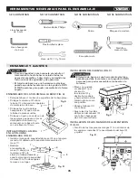
ASSEMBLY AND ADJUSTMENTS
11
1
Fig. M
3
4
5
2
10
8
9
11
6
7
10
Fig. N
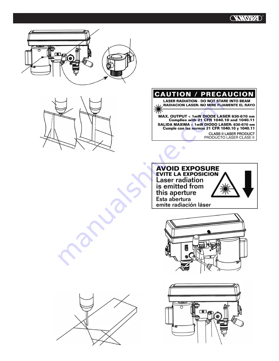
Vertical Alignment (Fig. M, N)
• Loosen the hex screws (3) using a 3 mm hex wrench,
manually rotate the laser adjusting knob (5) and move
the board from side to side as required until the laser
beam (10) lines up with the marked line (7). Keep
adjusting until the laser beam (10) and the marked line (7)
are aligned. Then carefully tighten the hex screws (3).
• Adjust the other laser beam (11) in the same manner.
Two parallel laser beams (10, 11) should look like
the right side drawing in Fig. N.
NOTE:
The distance between the laser beams will vary
with board thickness; however, the laser beams must be
parallel.
Crosshairs Alignment (Fig. M, O)
• Place a board (12) flat on the table. Do not allow the board
to move from this position; use clamps if needed. Bring
the bit down until it leaves a slight perforation in the
board; then raise it back up.
• Using a 10 mm wrench, slightly loosen the nut (4) so
the laser beam crosses the perforation (13).
Tighten the nut (4).
• Adjust the other laser assembly in the same manner until
the laser beams form crosshairs (14) exactly over
the perforation (13) on the board (12).
• Re-check the vertical alignment
to ensure that the laser
beams did not shift during
the tightening process.
The drilling hole
is now at the center
of crosshairs for
accurate drilling.
• Replace the covers (1)
with the screws (2)
over the laser
assembly on
each side.
14
12
13
Fig. O
LASER LABEL (FIG. P)
For your convenience and safety, the following labels are
on your laser.
The label (1) on your laser may include the following symbols.
(Fig. P)
V ................................................................................. volts
mW .......................................................................... milliwatts
nm ............................................... wavelength in nanometers
II .................................................................... Class Il Laser
Laser Aperture Label (2): AVOID
EXPOSURE: Laser radiation is emitted from this aperture.
(Fig. P)
2
1
2
Fig. P
Summary of Contents for KN DP-2000N
Page 1: ...KN DP 2000N Bench drill press8 Taladro de columna de banco 203 2 mm ...
Page 18: ...EXPLODED VIEW 17 Bench drill press8 Taladro de columna de banco 203 2 mm KN DP 2000N ...
Page 36: ...Bench drill press8 Taladro de columna de banco 203 2 mm KN DP 2000N DIAGRAMA DE ENSAMBLADO 35 ...
Page 37: ...NOTES NOTAS 36 ...
Page 38: ...NOTES NOTAS 37 ...
Page 39: ...NOTES NOTAS 38 ...
Page 40: ...www knova com mx ...


