background image


For U.S.A. 

NOTE: This equipment has been tested and found to comply with the limits for a Class A 
digital device, pursuant to Part 15 of the FCC Rules. These limits are designed to provide 
reasonable protection against harmful interference in a residential installation. This 
equipment generates, uses and can radiate radio frequency energy and, if not installed in 
accordance with the instructions, may cause harmful interference to radio 
communications. However, there is no guarantee that interference will not occur in a 
particular installation. If this equipment does cause interference to radio or television 
reception, which can be determined by turning the equipment off and on, the user is 
encouraged to try to correct the interference by one or more of the following measures: 
Reorient or relocate the receiving antenna 
Increase the separation between the equipment and receiver 
Connect the equipment into an outlet on a circuit different from that to which the receiver 
is connected 
Consult the dealer or an experienced radio/TV technician for help 
 

For Canada/pour le Canada 

CAUTION:


TO PREVENT ELECTRIC SHOCK, MATCH WIDE BLADE OF 

PLUG TO WIDE SLOT, FULLY INSERT. ATTENTION: POUR EVITER LES 
CHOCS ELECTRIQUES, INTRODUIRE LA LAME LA PLUS LARGE DE LA FICHE 
DANS LA BORNE CORRESPONDANTE DE LA PRISE ET POUSSER JUSQUAU 
FOND.


This Class A digital apparatus complies with Canadian ICES-003. 

Cet appareil numérique de la Classe A est conforme à la norme NMB-003 du 
Canada.


• Do not block the ventilation openings or holes. 
(If the ventilation openings or holes are blocked by a newspaper or cloth, etc., the heat may not be 
able to get out.) 
• Do not place any naked flame sources, such as lighted candles, on the apparatus. 
• When discarding batteries, environmental problems must be considered and local rules or laws 
governing the disposal of these batteries must be followed strictly. 
• Do not use this apparatus in a bathroom or places with water. Also do not place any containers 
filled with water or liquids (such as cosmetics or medicines, flower vases, potted plants, cups, 
etc.) on top of this apparatus.


ATTENTION: 
• Ne bloquez pas es orifices ou es trous de ventilation. (Si es orifices ou es trous de ventilation 
sont bloqués par un journal un tissu, etc., la chaleur peut ne pas être évacuée correctement de 
l’appareil) 
• Ne placez aucune source de flamme nue, telle qu’une bougie, sur l’appareil. 

Summary of Contents for RSIII

Page 1: ...RSIII Routing Switcher Operation and Technical Manual Knox Video Technologies 8677 Grovemont Circle Gaithersburg MD 20877 301 840 5805 301 840 2946 Fax www knoxvideo com...

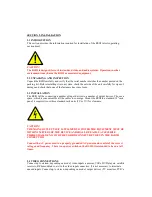
Page 2: ...CE PARTS INSIDE DO NOT ATEMPT TO PERFORM UNAUTHORIZED MODIFICATIONS DISCONNECT THE MAINS PLUG TO SHUT THE POWER OFF COMPLETELY The lightning flash with arrowhead symbol within an equilateral triangle...

Page 3: ...AUTION TO PREVENT ELECTRIC SHOCK MATCH WIDE BLADE OF PLUG TO WIDE SLOT FULLY INSERT ATTENTION POUR EVITER LES CHOCS ELECTRIQUES INTRODUIRE LA LAME LA PLUS LARGE DE LA FICHE DANS LA BORNE CORRESPONDANT...

Page 4: ...o human health and the environment by restricting the use of these hazardous substances in new equipment Manufacturers of electronics products outside Europe must abide by this legislation if the equi...

Page 5: ...en returning the product the defective product should be securely packaged in original boxes and insured for shipment Place the RA number on the outside and inside of the package Include a description...

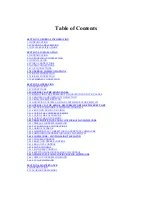
Page 6: ...3 4 CONTROL VIA THE SERIAL RS232 RS422 PORT OR ETHERNET PORT 3 4 1 LETTER COMMANDS SWITCHING CHANNELS 3 4 1 1 ROUTING AUDIO AND VIDEO 3 4 1 2 USING THE CONFERENCE MODE 3 4 1 3 USING THE SALVO MODE 3...

Page 7: ...coders Cross point information is collected by the microprocessor from the front panel controller the RS232 RS422 and Ethernet inputs on the rear panel Audio and video may be routed together or separa...

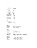
Page 8: ...z 70 dbu Crosstalk CH CH 20dbu 2kHz 100 db 20kHz 81 db CMMR 22Hz 22kHz 75 5 db Max Input Level 24 dbu Max Output Level 24 dbu Gain 0db unity Input Impedance 600 Ohms Output Impedance 600 Ohms Connecto...

Page 9: ...000 feet Connector RJ45 Control Front Panel Push buttons RS232 RS422 DB9 female Knox protocol 1 1 0 Ethernet RJ45 10 100 Auto sense Default IP 192 168 168 48 port 3001 General Temperature Operating 32...

Page 10: ...put devices Choose a space which is convenient for all the cables to converge Mount the RSIII in a standard 19 rack panel it requires two or three standard rack units 2U or 3U for clearance CAUTION TH...

Page 11: ...input and connecting the shield to both the center and inputs Connect up to sixteen depending on model audio output devices amplifiers PVR s tape CD recorders RF modulators etc to the left and right...

Page 12: ...or TCP IP Under Configure for a COM port set the baud rate to 9600 8 bits no parity 1 stop bit and no flow control for a TCP IP connection enter the IP address of the RSIII and enter port 3001 Click O...

Page 13: ...rom the factory is IP address 192 168 168 48 Subnet mask 24 Gateway 0 0 0 0 Port 3001 CAUTION When accessing the RSIII through the network connection security must be considered If the RSIII is connec...

Page 14: ...represents the enter key IP Address 192 168 48 1 ENTER Gateway Address 192 168 1 1 ENTER Netmask 24 ENTER Port 3001 ENTER Once properly configured access to the RSIII can only be gained by use of a us...

Page 15: ...array of up to 32 push button switches allows for the selection of crosspoints and storage recall of stored crosspoint patterns 3 3 1 DISPLAYING THE CROSSPOINT CONNECTIONS AND VTB VALUES In idle mode...

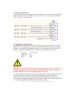
Page 16: ...he control device to 9600 baud 8 bits no parity and one or two stop bits flow control NONE When using the serial port mode the COM port of a PC compatible device may be connected to the rear DB9 conne...

Page 17: ...deo use 0 s for off To route audio only send a command in the form Axy ENTER Axxyy ENTER Axxxyyy ENTER Where x specifies the output to be routed to and where y specifies the input source of audio use...

Page 18: ...and o is the input number The Z command sends audio only to the range of outputs Zmno ENTER Zmmnnoo ENTER Zmmmnnnooo ENTER where m is the first output number n is the last output number and o is the i...

Page 19: ...Entire Crosspoint Matrix in single group DL Display Entire Crosspoint Matrix in Multicolumn Format DRxy Display Range of Crosspoint Matrix in single group DRxxyy DRxxxyyy Where x is the starting outp...

Page 20: ...t pattern to one of the sixteen pattern storage areas send a command in the form Sxx ENTER Where xx is 01 16 To store the current crosspoint pattern to the power up pattern type the command S ENTER S0...

Page 21: ...x is a command name will display specific help about using that command H ENTER Summary of help command Hx ENTER Specific help on command x H ENTER Crosspoint Commands Misc Commands B Follow Switch H...

Page 22: ...is sent The and signs are used to indicate the direction of the level change that is up or down respectively The polarity of the volume is displayed as a negative number when displayed or retrieved T...

Page 23: ...default value is 0 centered 3 4 3 4 MUTE CONTROL Individual outputs can be muted To mute the sound send the command Mxx1 ENTER for mute on Mxx0 ENTER for mute off default is off Where xx is the outpu...

Page 24: ...To send the command to all the outputs in Zone Group A omit the output number and precede the command with a ZA So the full command for the above example is ZA V3 The different zone commands are summ...

Page 25: ...mperature range No maintenance of the cooling system is required No other routine maintenance is required in the RSIII 4 2 CLEARING THE MEMORY Under certain circumstances the RSIII memory may become c...

Reviews: