background image

+

-

Шина KNX

USB

ETS

It is recommended to use USB cables that do not exceed 5 meters

Without connection to USB device is not powered! 

1.3  INSTALLATION AND CONNECTION

INSTALLATION

WIRING DIAGRAMS

Attaching to DIN rail

Removing from DIN rail

ATTENTION! 

Installation and connection of the device to the mains must only be carried 

out by qualified personnel! Be sure to turn off the power before installing or removing the 
device!  Even  when  the  device  is  turned  off,  the  output  terminals  can  be  live!  Do  not 
connect to the outputs a load that exceeds the recommended values! The design of the 
device meets the requirements of electrical safety according to GOST 12.2.007.0-75.

page 6

module-electronic.ru

Summary of Contents for Module IC-USB-S.1

Page 1: ...module electronic ru KNX USB INTERFACE IC USB S 1 Application Program ver 1 0 User Manual ver 1 0 User Manual ...

Page 2: ...pecification 4 1 2 Appearance 5 1 3 Installation and conection 6 2 Operational description 7 2 1 KNX programming interface 8 2 2 Individual address assignment 9 2 3 Project individual address 10 2 4 Group associations 11 page 2 module electronic ru ...

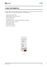
Page 3: ...the KNX network Protocol cEMI Common EMI Supports RAW Frame operation mode Interface USB 2 0 type B LED status indication Long telegrams with up to 220 bytes APDU length are supported USB and KNX TP galvanic isolation Power supply via USB Low power consumption DIN rail 35mm mounting IC USB S 1 1 BASIC INFORMATION page 3 module electronic ru ...

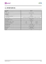
Page 4: ... standard cable TP1 0 8мм Ø Supported protocols cEMI Common EMI KNX physical address by default 0 2 255 Power supply via USB 5V DC Consumption on the KNX bus 29V DC 5mA 150mW Consumption on the USB 5V DC 20mA 100mW Operation temperature 5 C 45 C Operation humidity 5 95 no condensation Degree of protection IP 20 clean environment Mounting type DIN rail 35mm Dimensions 36 х 90 х 71mm 2TE Weight 62g ...

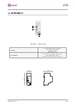
Page 5: ...X TP 1 State USB Green USB connection OK No telegram traffic Green blinking Telegram traffic Red USB Suspend Mode OFF No USB connection 2 Bus state KNX TP Green KNX TP connection OK No telegram traffic Green blinking Telegram traffic OFF KNX TP line not connected or no USB connection page 5 module electronic ru ...

Page 6: ...ION Installation and connection of the device to the mains must only be carried out by qualified personnel Be sure to turn off the power before installing or removing the device Even when the device is turned off the output terminals can be live Do not connect to the outputs a load that exceeds the recommended values The design of the device meets the requirements of electrical safety according to GO...

Page 7: ... connection is established Blinking green indicates the telegram traffic extent In Microso Windows the IC USB S 1 is recognized as HID Human Interface Device So no extra drivers have to be installed or downloaded The IC USB S 1 s ETS dummy database entry e g for connecting a visualization device is available for ETS4 and upward The database without parameters and without communication objects can b...

Page 8: ...rrent Interface in the ETS Bus Connections window or alternatively during editing a project at the bottom line Name and state of current connection of the ETS window 2 1 KNX PROGRAMMING INTERFACE Figure 1 ETS bus connection interface windows page 8 module electronic ru ...

Page 9: ... to the device by setting the desired address in the Individual Address field of the Bus Connections window of the ETS To download the desired Individual Address the IC USB S 1 has to be chosen as the Current Interface Then type in the Individual Address and press the Test button Figure 2 Individual addres assignment page 9 module electronic ru ...

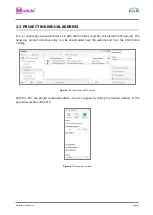
Page 10: ... The necessary product database entry can be downloaded from the website and from the KNX Online Catalog With the ETS the project Individual Address can be assigned by setting the desired address in the properties window of the ETS Figure 3 USB interface in the ETS catalog Figure 4 ETS properties window page 10 module electronic ru ...

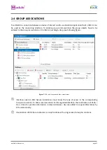
Page 11: ...e following figure Interfaces used in KNX Secure installations must know the type of access to the corresponding Group Associations To allow communication for the regarded interface the combination of PA IA GA is stored as position information in relevant devices GAs are added to coupler filter tables by ETS automatically Visualization of KNX Secure devices can only be done with using secured Group ...

Reviews:

Related manuals for Module IC-USB-S.1