background image

kobalttools.com

5

• 

DUST  PROTECTION. 

 Use  of  power  tools  can  generate  and/or  disperse  dust,  which  may  cause

  serious and permanent respiratory damage. Direct particles away from face and body. Always operate

  machines  in  well-ventilated  area  and  provide  for  proper  dust  removal.  Use  dust  collection  system

  wherever possible. Exposure to dust may cause serious and permanent respiratory or other injury,

  including  silicosis  (a  serious  lung  disease),  cancer,  and  death.  Avoid  breathing  dust  and  avoid

  prolonged contact with dust. Allowing dust to get into your mouth or eyes, or lay on your skin may

  promote absorption of harmful material. Use properly fitting NOISH/OSHA/MSHA approved respiratory

  protection appropriate for the dust exposure and wash exposed areas with soap and water.

• 

THIS PRODUCT WAS DESIGNED TO BE USED AS A STAND FOR MITER SAW AND PORTABLE


PLANERS. DO NOT

 alter the stand, use it with other products, or for other purposes. The stand will

  support 400 lbs., including both machine and work piece. Any misuse or abuse can result in product

  damage or personal injury.

• 

USE CARE WHEN ASSEMBLING, MOVING, RAISING OR LOWERING THE STAND

 to reduce the

  risk of pinching hands and fingers.

• 

PLACE THE STAND ON A FLAT AND LEVEL SURFACE

 to prevent rocking or tipping. Do not use

  the stand on an uneven, unstable or slippery surface. Always check the stability of the stand before

  connecting machine to power source.

• 

DO NOT STAND ON THIS PRODUCT

 or use the support extensions as a ladder or scaffolding. It is

  unsafe to climb, sit or stand on this product. 

• 

CHECK PRODUCT FOR DAMAGE.

 Before using stand, and after it has been dropped or damaged,

  check moving and affected components of stand and any attached machines for alignment, binding,

  breakage and any other condition that may affect the machine’s performance and the stand’s ability

  to properly support and secure the machine. Do not use a damaged product. A damaged product

  should be properly repaired using only identical replacement parts.

• 

CHECK THE LEGS AND OTHER SUPPORTS

 to confirm that they are properly locked in place before

  connecting machine to power source.

• 

DISCONNECT MACHINE

 from power source before attaching it to stand, and when machine is not

  in use. 

• 

PROPERLY MOUNT

 machine and adjust work piece supports so the work piece(s) will be level with

  machine table. 

• 

PROPERLY SECURE THE MACHINE

 to the stand before connecting it to power source.

• 

DO NOT ATTEMPT

 to use stand for operations involving awkward or oversized work pieces that

  could cause the stand to tip over.

• 

WHEN TRANSPORTING STAND,

 make sure it is properly secured to prevent movement and possible

  damage.

SAVE THESE INSTRUCTIONS

• Refer to them often and use them to instruct others.

• If stand is loaned to someone, also loan them these instructions.

If you have any questions or concerns relative to the use of your tool or the contents of this manual,

stop using the tool and contact our customer service department at 1-888-3KOBALT (1-888-356-2258)

8 a.m. -8 p.m., EST Monday-Friday.

SAFETY INFORMATION

Summary of Contents for 0786032

Page 1: ...ts Before returning to your retailer call our customer service department at 1 888 3KOBALT 1 888 356 2258 8 a m 8 p m EST Monday Friday ATTACH YOUR RECEIPT HERE Serial Number Purchase Date Español p 35 Français p 18 MODEL KMS S16 ITEM 0786032 MITER SAW STAND ...

Page 2: ...Safety Information Preparation Assembly Instructions Operating Instructions Adjustment Instructions Care and Maintenance Three Year Warranty Replacement Parts List DESCRIPTION SPECIFICATIONS Stand height to mounting brackets 32 1 4 in Size of the extended stand 99 6 in x 29 5 in x 35 4 in Extension arm length 96 in Maximum load capacity 400 lbs ...

Page 3: ... PART DESCRIPTION QUANTITY Hardware for handle Hardware for wheels Miter saw mounting hardware Bolt M8 x 90mm Qty 2 Wheel Sleeve Qty 2 Spring Washer 6 Qty 4 Flat Washer 6 Qty 2 Flat Washer 6 Qty 4 Hexagon Bolt M6 x 30mm Qty 2 Washer 14 Qty 2 Big Flat Washer 8 Qty 2 Washer 10 Qty 2 Locking Nut M8 Qty 2 Hexagon Bolt M6 x 55mm Qty 4 II JJ CC JJ AA DD EE GG FF HH BB A B C E F D G ...

Page 4: ...sult in death or serious injury CAUTION Indicates a potentially hazardous situation which if not avoided may result in minor or moderate injury WARNING KEEP WORK AREA CLEAN AND WELL LIT Cluttered or poorly lit work areas surfaces and benches can lead to accidents Do not leave anything on stand when machine is in use Allow enough room and provide proper support for work piece and operation of the m...

Page 5: ...DO NOT STAND ON THIS PRODUCT or use the support extensions as a ladder or scaffolding It is unsafe to climb sit or stand on this product CHECK PRODUCT FOR DAMAGE Before using stand and after it has been dropped or damaged check moving and affected components of stand and any attached machines for alignment binding breakage and any other condition that may affect the machine s performance and the s...

Page 6: ...h ASSEMBLY INSTRUCTIONS UNPACKING This product requires assembly 1 Carefully remove the stand and all parts from the carton 2 Separate all parts from the packing materials Compare parts with the illustration on page 3 to make sure all parts are found 3 Do not discard the packing material until you have carefully inspected and satisfactorily operated the stand PREPARING THE STAND 1 Lay the miter sa...

Page 7: ...ND With the stand open and resting on a flat and level surface the stand should not move or rock from side to side If the stand rocks from side to side the adjustable foot J needs adjusting until the stand is balanced 1 Lift the stand slightly so that you may turn the adjustable foot J until the stand no longer rocks 2 Turning clockwise will lower the foot 3 Turning counterclockwise will raise the...

Page 8: ...with holes on the miter saw stand D Insert the hexagon bolts M6 x 30 mm CC through flat washers 6 JJ and into the mounting holes on the handle and miter saw stand Tighten the hexagon bolts M6 x 30mm CC with 5mm hex key G Hardware Used 2 Attach two wheels B to the miter saw stand D with two bolts M8 x 90mm AA washers 14 EE washers 10 FF wheel sleeves DD big flat washers 8 GG and locking nuts M8 HH ...

Page 9: ... and stability All corners of the saw must be bolted securely to the mounting brackets before use Make sure no bolts extend above the saw table Note Only 4 sets of securing hardware are provided with the stand If this provided hardware does not work with your saw use hardware that will properly secure you saw Mounting brackets when slots align with saw mounting holes 1 Unplug saw and lock cutting ...

Page 10: ...h the other end of the same bracket Hardware Used 3 Place the second saw mounting bracket underneath the other side of the saw aligning the mounting holes on the miter saw base with the nut inside the top of bracket Install hexagon bolts M6 x 55mm as previously described Hardware Used 4 After making sure both brackets are parallel to each other tighten all four hexagon bolts M6 x 55mm with 5mm hex...

Page 11: ...sition Mount the saw to a mounting surface at least 1 2 in thick using 5 16 in hexagon bolts washers and nuts not included 2 Drill holes in the mounting surface to match the slots in the saw mounting brackets Proceed with installation as previously described Hardware Used Hexagon bolt M6 x 55mm x 4 BB Spring washer 6 x 4 II Flat washer 6 x 4 JJ ASSEMBLY INSTRUCTIONS ...

Page 12: ...s in position by lowering the locking levers L Note Continue to hold the mounting bracket assembly with one hand until both levers are securely locked 3 Check position and adjust if necessary to make sure the weight of the saw is evenly balanced over the rails Ensure the saw is fully seated and locked in position To remove saw from stand 1 Raise the locking levers to unlock the saw and mounting br...

Page 13: ...ment knob M Extend the rail N to the desired position Tighten the extension adjustment knob M USING THE WORK SUPPORTS Raise the work supports whenever you need to make repetitive cuts of the same size To avoid a greater risk of binding or pinching do not use both work supports at the same time To raise the work supports Loosen the work support adjustment knob O Raise the work support A to the desi...

Page 14: ...ting the stand to its vertical storage position Always fully tighten all the mounting bolts nuts and locking knobs Failure to do so could result in serious personal injury To fold up two legs located on the same side as the wheel press the locking pins I and push the legs up toward the stand until they click into place To fold up the other legs press the locking pins I and push the legs up toward ...

Page 15: ... from the rails when the levers are locked the bracket adjustment bolts need to be tightened If the saw and bracket assembly will not fit over both rails the bracket adjustment bolts need to be loosened Note The saw should be removed from the mounting brackets before attempting to tighten or loosen the bracket adjustment bolts To adjust Turn the bolt T with 5mm hex key Rotate clockwise if the brac...

Page 16: ...l beyond capacity improper maintenance neglect or accident or the damage is due to the use of the tool after partial failure or use of improper accessories or unauthorized repair or alteration This warranty gives you specific legal rights and you may also have other rights that vary from state to state For questions warranty claims and or warranty replacement parts call our customer service depart...

Page 17: ... KOBALT and the K Design are registered trademarks of LF LLC All Rights Reserved B C A F G E LL KK MM A Left work support 786032001 B Wheel 786032002 C Mounting bracket 786032003 E Right work support 786032004 F Handle 786032005 G 5mm Hex key 786032006 KK Miter saw mounting hardware 786032007 LL Hardware for handle 786032008 MM Hardware for wheels 786032009 PART DESCRIPTION PART ...

Page 18: ...es Avant de retourner l article au détaillant appelez notre service à la clientèle au 1 888 3KOBALT 1 888 356 2258 entre 8 h et 20 h HNE du lundi au vendredi JOIGNEZ VOTRE REÇU ICI Numéro de série Date d achat MODÈLE KMS S16 ARTICLE 0786032 SUPPORT POUR SCIE À ONGLET ...

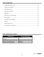
Page 19: ...écurité Préparation Instructions pour l assemblage Mode d emploi Instructions pour le réglage Entretien Garantie de trois ans Liste des pièces de rechange CARACTÉRISTIQUES Hauteur du support jusqu aux supports de fixation 81 91 cm Dimensions du support lorsque déplié 253 00 cm x 74 93 cm x 89 91 cm Longueur du bras d extension 243 84 cm Capacité de charge maximale 181 43 kg DESCRIPTION ...

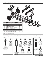
Page 20: ...QUANTITÉ Quincaillerie pour la poignée Quincaillerie pour les roues Quincaillerie de fixation de la scie à onglet Boulon M8 de 90 mm Qté 2 Manchon pour roue Qté 2 Rondelle à ressort 6 Qté 4 Rondelle plate 6 Qté 2 Rondelle plate 6 Qté 4 Boulon hexagonal M6 de 30 mm Qté 2 Rondelle 14 Qté 2 Grande rondelle plate 8 Qté 2 Rondelle 10 Qté 2 Écrou de blocage M8 Qté 2 Boulon hexagonal M6 de 55 mm Qté 4 II...

Page 21: ...pas éliminé pourrait provoquer des blessures mineures ou moyennement graves AVERTISSEMENT MAINTENEZ L AIRE DE TRAVAIL PROPRE ET BIEN ÉCLAIRÉE Une aire de travail et un établi encombrés et peu éclairés sont propices aux accidents Ne laissez rien sur le support lorsque l outil est utilisé Laissez suffisamment d espace et fournissez un soutien adéquat à la pièce travaillée pour assurer un bon fonctio...

Page 22: ...ter un balancement ou un basculement N utilisez pas le support sur une surface inégale instable ou glissante Avant de brancher l appareil vérifiez toujours la stabilité du support NE VOUS TENEZ PAS DEBOUT SUR CET ARTICLE et n utilisez pas les supports réglables comme échelle ou comme échafaudage Il n est pas sécuritaire de grimper de s asseoir ou de se tenir debout sur ce produit ASSUREZ VOUS QUE ...

Page 23: ...proximatif 4 minutes Outils nécessaires pour l assemblage non inclus clé de 13 mm ou clé à molette INSTRUCTIONS POUR L ASSEMBLAGE DÉBALLAGE Ce produit nécessite un assemblage 1 Retirez soigneusement le support et toutes les pièces de la boîte 2 Retirez toutes les pièces du matériel d emballage Comparez les pièces avec l illustration de la page 3 pour vous assurer d avoir toutes les pièces 3 Ne jet...

Page 24: ... sur une surface plane et de niveau il ne devrait pas bouger ni se balancer d un côté à l autre Si le support se balance d un côté à l autre le patin réglable J doit être ajusté jusqu à ce que le support soit stable 1 Soulevez légèrement le support pour que vous puissiez tourner le patin réglable J jusqu à ce que le support ne se balance plus 2 Pour descendre le pied tournez dans le sens des aigui...

Page 25: ...z les boulons hexagonaux M6 de 30 mm CC dans les rondelles plates 6 JJ et dans les trous de fixation sur la poignée et le support pour scie à onglet Serrez les boulons hexagonaux M6 de 30 mm CC à l aide de la clé hexagonale de 5 mm G Quincaillerie utilisée 2 Fixez deux roues B au support pour scie à onglet D à l aide de deux boulons M8 de 90 mm AA de rondelles 14 EE de rondelles 10 FF de manchons ...

Page 26: ...ins de la scie doivent être boulonnés aux supports de fixation avant l utilisation Assurez vous qu aucun boulon ne dépasse de la table de la scie Remarque Il n y a que quatre ensembles de quincaillerie de fixation fournis avec le support Si cette quincaillerie n est pas compatible avec votre scie utilisez une quincaillerie qui permettra de fixer votre scie adéquatement Installez les supports de fi...

Page 27: ...caillerie utilisée 3 Placez le deuxième support de fixation de la scie sous l autre côté de la scie en alignant les trous de montage du socle de la scie à onglet sur l écrou à l intérieur de la partie supérieure du support Installez les boulons hexagonaux M6 de 55 mm comme décrit précédemment Quincaillerie utilisée 4 Après vous être assuré que les deux supports étaient en position parallèle serrez...

Page 28: ...ace de montage d une épaisseur minimale de 1 27 cm à l aide de boulons hexagonaux de rondelles et d écrous de 5 16 po non inclus 2 Percez des trous dans la surface de montage pour les aligner sur les fentes des supports de fixation de la scie Procédez à l installation comme décrit précédemment Quincaillerie utilisée Boulon hexagonal Boulon M6 de 55 mm x 4 BB Rondelle à ressort 6 x 4 II Rondelle pl...

Page 29: ... blocage L Remarque Continuez de tenir l ensemble du support de fixation d une main jusqu à ce que les leviers soient bien verrouillés 3 Vérifiez l emplacement de la scie et ajustez le au besoin pour vous assurer que le poids de la scie est bien équilibré sur les traverses Assurez vous que la scie est bien en place et verrouillée Pour retirer la scie du support 1 Élevez les leviers de blocage pour...

Page 30: ...N pour la placer à la position désirée Serrez le bouton de réglage d extension M UTILISATION DES SUPPORTS DE PIÈCE Relevez les supports de pièce lorsque vous avez besoin de faire des coupes répétitives de la même taille Pour éviter un plus grand risque de coincement ou de pincement n utilisez pas les deux supports de pièce simultanément Pour relever les supports de pièce Desserrez le bouton de rég...

Page 31: ... de rangement verticale Serrez toujours complètement tous les boulons de montage les écrous et les boutons de blocage Sinon vous risquez de subir de graves blessures Pour replier les deux pieds qui se trouvent du même côté que la roue appuyez sur les goupilles d arrêt I et poussez sur les pieds vers le haut en direction du support jusqu à ce qu ils s enclenchent Pour replier les autres pieds appuy...

Page 32: ...ers sont verrouillés les boulons de réglage du support doivent être serrés Si l ensemble de la scie et du support ne s insère pas sur les deux traverses les boulons de réglage du support doivent être desserrés Remarque Vous devez retirer la scie des supports de fixation avant de serrer ou de desserrer les boulons de réglage du support Pour ajuster Tournez le boulon T à l aide de la clé hexagonale ...

Page 33: ...sultant de l utilisation de l outil après une défaillance partielle ou de la réparation ou de la modification non autorisées avec des accessoires inadéquats Cette garantie vous confère des droits précis Il est possible que vous disposiez également d autres droits qui varient d un État ou d une province à l autre Pour toute question ou réclamation au titre de la garantie ou pour obtenir des pièces ...

Page 34: ...e K sont des marques de commerce déposées de LF LLC Tous droits réservés B C A F G E LL KK MM A Support de pièce gauche 786032001 B Roue 786032002 C Support de fixation 786032003 E Support de pièce droit 786032004 F Poignée 786032005 G Clé hexagonale de 5 mm 786032006 KK Quincaillerie de fixation de la scie à onglet 786032007 LL Quincaillerie pour la poignée 786032008 MM Quincaillerie pour les rou...

Page 35: ...r a la tienda llame a nuestro Departamento de Servicio al Cliente al 1 888 3KOBALT 1 888 356 2258 de lunes a viernes de 8 a m a 8 p m hora estándar del Este ADJUNTE SU RECIBO AQUÍ Número de serie Fecha de compra MODELO KMS S16 ARTÍCULO 0786032 BASE PARA SIERRA INGLETADORA ...

Page 36: ...ración Instrucciones de ensamblaje Instrucciones de funcionamiento Instrucciones de ajuste Cuidado y mantenimiento Garantía de tres años Lista de piezas de repuesto ESPECIFICACIONES Altura de la base a los soportes de montaje 81 91 cm Tamaño de la base extendida 253 00 cm x 74 93 cm x 89 91 cm Longitud del brazo de extensión 243 84 cm Capacidad máxima de carga 181 43 kg DESCRIPCIÓN ...

Page 37: ...N CANTIDAD Aditamentos para la manija Aditamentos para la ruedas Aditamentos de montaje de la sierra ingletadora Perno M8 x 90 mm Cant 2 Manguito de la rueda Cant 2 Arandela de resorte No 6 Cant 4 Arandela plana No 6 Cant 2 Arandela plana No 6 Cant 4 Perno hexagonal M6 x 30 mm Cant 2 Arandela No 14 Cant 2 Arandela plana grande No 8 Cant 2 Arandela No 10 Cant 2 Contratuerca M8 Cant 2 Perno hexagona...

Page 38: ...rse podría ocasionar lesiones menores o moderadas ADVERTENCIA MANTENGA EL ÁREA DE TRABAJO LIMPIA Y BIEN ILUMINADA Si las áreas de trabajo las superficies y los bancos están desordenados y tienen poca iluminación aumenta el riesgo de que ocurran accidentes No apoye ningún objeto sobre la base cuando la máquina esté en funcionamiento Asegúrese de contar con el espacio suficiente y con una buena supe...

Page 39: ...evitar que se balancee o incline No use la base sobre una superficie dispareja inestable o resbalosa Verifique que la base esté nivelada antes de conectar la máquina a una fuente de alimentación NO SE PARE SOBRE ESTE PRODUCTO ni use las extensiones del soporte como escalera o andamio No es seguro subirse sentarse ni pararse sobre este producto REVISE EL PRODUCTO PARA VERIFICAR QUE NO ESTÉ DAÑADO S...

Page 40: ...as necesarias para el ensamblaje no se incluyen llave ajustable o de 13 mm INSTRUCCIONES DE ENSAMBLAJE DESEMBALAJE Este producto requiere de ensamblado 1 Retire cuidadosamente la base y todas las piezas de la caja 2 Separe todas las piezas del material de embalaje Compare las piezas con la imagen de la página 3 para asegurarse de que estén todas las piezas 3 No deseche el material de embalaje hast...

Page 41: ...ase está abierta e instalada sobre una superficie plana y nivelada no debe moverse ni balancearse Si la base se mueve de un lado al otro la pata ajustable J debe ajustarse hasta que la base esté nivelada 1 Levante la base levemente de modo que pueda girar la pata ajustable J hasta que la base deje de balancearse 2 Si la gira en dirección de las manecillas del reloj la pata se bajará 3 Si la gira e...

Page 42: ...D Inserte los pernos hexagonales M6 x 30 mm CC en las arandelas planas No 6 JJ y en los orificios de montaje de la manija y de la base de la sierra ingletadora Apriete los pernos hexagonales M6 x 30 mm CC con una llave hexagonal de 5 mm G Aditamentos utilizados 2 Coloque dos ruedas B en la base de la sierra ingletadora D con dos pernos M8 x 90 mm AA dos arandelas No 14 EE dos arandelas No 10 FF do...

Page 43: ...es de usar la herramienta deben empernarse las cuatro esquinas de la sierra a los soportes de montaje Asegúrese de que los pernos no se extiendan por sobre la mesa de la sierra Nota la base solo viene con 4 juegos de aditamentos de seguro Si los aditamentos proporcionados no funcionan con la sierra use aditamentos que permitan fijar la sierra a la base correctamente Soportes de montaje cuando las ...

Page 44: ...o de la misma abrazadera Aditamentos utilizados 3 Coloque el segundo soporte de montaje de la sierra debajo del otro lado de la sierra y alinee los orificios de montaje de la base de la sierra ingletadora con la tuerca que se encuentra dentro de la parte superior de la abrazadera Coloque los pernos hexagonales M6 x 55 mm tal como se describe anteriormente Aditamentos utilizados 4 Verifique que amb...

Page 45: ...cie de montaje de 1 27 cm de espesor como mínimo para ello use pernos hexagonales de 0 79 cm arandelas y tuercas no se incluyen 2 Taladre orificios en la superficie de montaje que coincidan con las ranuras de los soportes de montaje de la sierra Continúe con la instalación tal como se describe anteriormente Aditamentos utilizados Perno hexagonal M6 x 55 mm x 4 BB Arandela de resorte No 6 x 4 II Ar...

Page 46: ...ara trabar las abrazaderas en su lugar Nota siga sosteniendo el ensamble del soporte de montaje con una mano hasta que ambas palancas se hayan trabado de forma segura 3 Verifique la posición y si es necesario ajústela para asegurarse de que el peso de la sierra esté equilibrado en los rieles Asegúrese de que la sierra esté asentada y asegurada correctamente en su lugar Para retirar la sierra de la...

Page 47: ... riel N a la posición deseada Apriete la perilla de ajuste de extensión M USO DE LOS SOPORTES PARA TRABAJOS Levante los soportes para trabajos cada vez que tenga que realizar cortes repetitivos del mismo tamaño Para evitar el riesgo de que se produzcan atascamientos o pellizcos no use ambos soportes para trabajos al mismo tiempo Para levantar los soportes para trabajos Afloje la perilla de ajuste ...

Page 48: ...enamiento vertical Apriete completamente todos los pernos de montaje las tuercas y las perillas de fijación No hacerlo podría provocar lesiones personales graves Para plegar las dos patas que se encuentran del mismo lado que la rueda presione los pernos de fijación I y desplace las patas hacia arriba hacia la base hasta que encajen en su lugar Para plegar las otras patas presione los pernos de fij...

Page 49: ...stán bloqueadas deben apretarse los pernos de ajuste de la abrazadera Si el ensamble de la abrazadera y la sierra no encajan en ambos rieles deben aflojarse los pernos de ajuste de la abrazadera Nota es necesario retirar la sierra de los soportes de montaje antes de intentar apretar o aflojar los pernos de ajuste de la abrazadera Para realizar ajustes Gire el perno T con la llave hexagonal de 5 mm...

Page 50: ...imiento inadecuado una negligencia o un accidente el daño se debe al uso de la herramienta después de una falla parcial el uso con accesorios inadecuados o reparaciones o alteraciones no autorizadas Esta garantía le otorga derechos legales específicos pero es posible que también tenga otros derechos que varían según el estado Para hacer consultas o reclamos de garantía o solicitar piezas de repues...

Page 51: ...rcas registradas de LF LLC Todos los derechos reservados B C A F G E LL KK MM A Soporte para trabajos del lado izquierdo 786032001 B Rueda 786032002 C Soporte de montaje 786032003 E Soporte para trabajos del lado derecho 786032004 F Manija 786032005 G Llave hexagonal de 5 mm 786032006 KK Aditamentos de montaje de la sierra ingletadora 786032007 LL Aditamentos para la manija 786032008 MM Aditamento...

Reviews: