background image

TABLE  OF  CONTENTS

2

Safety  Information  ............................................................................................... 3

0

1

  .

..

..

..

..

..

..

..

..

..

..

..

..

..

..

..

..

..

..

..

..

..

..

..

..

..

..

..

..

..

..

..

..

..

..

..

..

..

..

..

..

..

..

..

..

..

..

..


s

t

n

e

t

n

o

C


e

g

a

k

c

a

P

0

..

..

..

..

..

..

..

..

..

..

..

..

..

..

..

..

..

..

..

..

..

..

..

..

..

..

..

..

..

..

..

..

..

..

..

..

..

..

..

..

..

..

..

..

..

..

..

..

..

..

..

..

..


n

o

it

a

r

a

p

e

r

P

1

1 .

..

..

..

..

..

..

..

..

..

..

..

..

..

..

..

..

..

..

..

..

..

..

..

..

..

..

..

..

..

..

..

..

..

..

..

..

..

..

..

..

..

..

..

..

s

n

o

it

c

u

rt

s

n

y

l

b

m

e

s

s

A

Operating Instructions ........................................................................................ 13

Care and Maintenance ....................................................................................... 14

Troubleshooting .................................................................................................. 15

Warranty ............................................................................................................. 15

6

1

 .

..

..

..

..

..

..

..

..

..

..

..

..

..

..

..

..

..

..

..

..

..

..

..

..

..

..

..

..

..

..

..

..

..

..

..

..

..

..

..

..

..

..


..

..

..

..

..

..

..

.

w

e

i

V


d

e

d

o

l

p

x

E

Product Specifications .......................... .............................................................. 3

Compressor Requirements .................................................................................. 2

6.4

CFM

90

PSI

Tool Requirements

Exigences relatives aux outils

Requisitos de herramientas

@

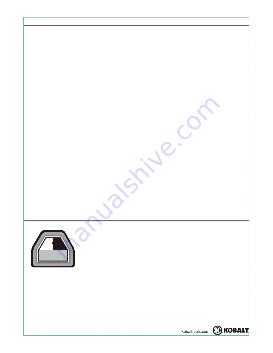
COMPRESSOR REQUIREMENTS

IMPORTANT:

 To operate correctly, 

this tool requires airflow of at least 6.4 cubic feet per 

minute (CFM) at 90 pounds per square inch (PSI) at the tool. 

Air hoses may cause loss in pressure up to 15 PSI, requiring a higher compressor output to 

compensate and maintain required pressure at the tool. Check the specifications of your air 

compressor to be sure that it can support both the CFM and PSI required by this specific tool.

Summary of Contents for SGY-AIR142TZ

Page 1: ...OUR RECEIPT HERE Serial Number Purchase Date 1 AB14953 KOBALT and the K Design are registered trademarks of LF LLC All Rights Reserved Questions problems missing parts Before returning to your retailer please call our customer service department at 1 888 3KOBALT 8 00 a m 8 00 p m EST Monday Friday ...

Page 2: ... Tool Requirements Exigences relatives aux outils Requisitos de herramientas COMPRESSOR REQUIREMENTS IMPORTANT To operate correctly this tool requires airflow of at least 6 4 cubic feet per minute CFM at 90 pounds per square inch PSI at the tool Air hoses may cause loss in pressure up to 15 PSI requiring a higher compressor output to compensate and maintain required pressure at the tool Check the ...

Page 3: ...ly Do not use this product in unsafe work conditions It is always recommended to keep a fire extinguisher and first aid kit near work areas FAILURE TO OBSERVE AND FOLLOW SAFETY INSTRUCTIONS COULD RESULT IN INJURY OR DEATH Some dust created by paint spraying power sanding sawing grinding drilling and other related activities is known to the State of California to cause cancer birth defects and othe...

Page 4: ...ARNING RISK OF LOSS OF HEARING Always wear ANSI S3 19 hearing protection Exposure to noise produced by air tools can lead to permanent hearing loss Compressed air can be hazardous propelling objects or particles that can cause injury into soft tissues such as eyes and ears Never direct air at yourself or anyone else For additional protection use an approved face shield in addition to safety glasse...

Page 5: ...ction where they contact the workpiece Keep the working part of the tool away from hands and body Do not touch accessories with bare hands during or immediately after use WHAT COULD HAPPEN HOW TO PREVENT IT WARNING RISK OF FIRE OR EXPLOSION Never use oxygen carbon dioxide or other bottled gasses as a power source for air tools Use only clean dry air at the specified pressure Wiping or cleaning rag...

Page 6: ...me into contact with hidden electrical wiring could cause electrocution or death Avoid body contact with grounded surfaces such as pipes radiators refrigerators and ranges There is an increased risk of electrical shock if your body is grounded Whenever possible it is recommended that electrically non conductive clothing and non skid foot wear be worn when using tools Thoroughly investigate workpie...

Page 7: ...ure the workpiece is secure Use clamps or other devices to prevent movement Loss of control of the tool can lead to operator injury or injury to others in the work area Never carry the tool by the air hose Never yank the air hose to disconnect it from the tool or the air supply Always carry the tool by the handle Avoid unintentional operation Never carry the tool with the trigger depressed or enga...

Page 8: ...pears to malfunction Never use tools which are leaking air or have missing parts Remove damaged or malfunctioning tools from the workplace immediately WHAT COULD HAPPEN HOW TO PREVENT IT WA RNING RISK OF PERSONAL INJURY SAFETY INFORMATION There is a risk of bursting if the tool is damaged Poor quality improper or damaged attachments can detach or fly apart during operation sending projectiles thro...

Page 9: ...or accessories Discontinue use of tool if discomfort tingling feeling or pain occurs Consult a physician before resuming use if any of these symptoms occur WHAT COULD HAPPEN HOW TO PREVENT IT WA RNING RISK OF PERSONAL INJURY SAFETY INFORMATION WHAT COULD HAPPEN HOW TO PREVENT IT WA RNING INHALATION HAZARD Abrasive tools such as grinders sanders and cut off tools generate dust and abrasive material...

Page 10: ... oil in this tool Sandpaper PACKAGE CONTENTS PREPARATION DESCRIPTION 6 in Palm Sander Sanding Pad Crank Shaft Air Regulator Knob Trigger Air Inlet Vacuum Adapter Revolving Tube Attachment QUANTITY 1 1 1 1 1 1 1 1 1 PART A B C D E F G H Protective Cap I 1 Wrench AA HARDWARE CONTENTS A E B C G H F I D AA Before assembling this tool make sure all parts are present Compare parts with package contents ...

Page 11: ...the wrench AA between the sander and sanding pad and secure the crank shaft as shown in Fig 3 Using the wrench to hold the crank shaft so it can t spin turn the sanding pad clockwise to make sure it is tightly attached NOTE To remove or replace the sanding pad use this same procedure to secure the crank shaft Unscrew the sanding pad by turning it counterclockwise To replace the pad make sure the t...

Page 12: ...sing an in line oiler 7 Connect the air supply hose to the male plug as shown in Fig 5 making sure it is completely seated and secure Set the working pressure at 90 PSI for best tool performance NOTE To operate correctly this tool requires airflow of at least 6 4 cubic feet per minute CFM at 90 pounds per square inch PSI at the tool 8 This tool features a vacuum adapter G with revolving tube attac...

Page 13: ...ed when the knob indicator is fully backward 2 To sand a workpiece first ensure that tool speed is set to the slowest setting Slowly press the trigger E to start the tool as shown in Fig 1 It may be helpful to support the tool with both hands during startup 3 Gradually increase tool speed as needed for your particular sanding application NEVER start sanding with the tool at the highest speed setti...

Page 14: ...n of oil collects on the paper the oiler is properly adjusted Excessive amounts of oil should be avoided Clean the entire tool with a cotton rag after each use If storing the tool for an extended period it should be lubricated and run for approximately 30 seconds to ensure oil has been evenly distributed throughout the tool Always store tools in a clean dry environment away from the reach of child...

Page 15: ...ressor manual Oil the tool and run until no water is evident Oil the tool again and run 1 2 seconds This tool is warranted by the manufacturer to the original purchaser from the original purchase date for three 3 years subject to the warranty coverage described herein This tool is warranted to the original user to be free from defect in material and workmanship If you believe that a tool is defect...

Page 16: ... Cover Set Ring Snap ring Bearin Washer Washer g Rear plate Rotor Rotor blade Cylinder Front plate O ring Lock ring Crank shaft Semi round key Screw Screw Bearing Bearing seal Bearing shield Snap ring Balance seat Pad cover Trigger lever Pin Pin Pin E clip Valve stem O ring O ring O ring Air regulator Spring O ring O ring Regulator cap Vacuum adapter Outlet bushing Air inlet Revolving Tube Attachm...

Reviews: