background image


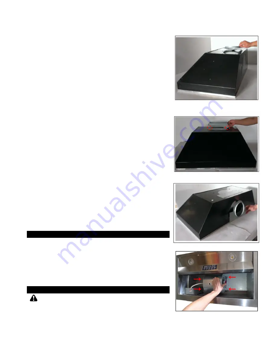
NOTE: The blower is pre-installed for top vent.   If 
installing as rear vent, follow the steps below.  

9.  For Rear 6” round installation only: 

Remove  the  Rear  Round  Vent  Cover  and  Rear 
Rectangular  Vent  Cover  (Refer  to  Figure  4).    Keep 
screws to attach Round Exhaust Plate to rear vent.  

Remove the pre-installed Round Exhaust Plate from top 
vent (Refer to Figure 5). Attach it to the rear vent (Refer 
to Figure 7) using the screws removed from vent covers.  

Use  the  Round  and  Rectangular  vent  covers  removed 
from rear vent to seal top vent.  

Remove  the  4  screws  that  secure  the  blower  system 
(Refer  to  Figure  8).  Hold  the  blower  to  keep  it  from 
dropping  as  you  remove  screws.  Keep  screws  to  re-
attach blower. Slowly rotate blower system to align with 
mounting holes at the back of the hood. Secure blower 
using 4 screws (Refer to Figure 9).  

10.  For Rear 3-1/4” x 10” rectangular installation only: 

Remove  the  Rear  Round  Vent  Cover  and  Rear 
Rectangular  Vent  Cover  (Refer  to  Figure  5).    Keep 
screws  to  attach  Rectangular  Exhaust  Plate  and 
Rectangular Exhaust Adapter.  

Place  the  Rectangular  Exhaust  Plate  over  vent  and 
secure  with  2  screws  (Refer  to  Figure  10).  Place 
Rectangular  Exhaust  Adapter  over  the  Rectangular 
Exhaust  Plate  and  secure  with  10  screws  (Refer  to 
Figure 10).  

Use remaining screws to secure exhaust plate.  

Remove the pre-installed Round Exhaust Plate from top 
vent and keep screws (Refer to Figure 4). Use the Round 
and Rectangular vent covers removed from rear to seal 
top vent.  

Remove  the  4  screws  that  secure  the  blower  system 
(Refer  to  Figure  8).  Hold  the  blower  to  keep  it  from 
dropping  as  you  remove  screws.  Keep  screws  to  re-
attach blower. Slowly rotate blower system to align with 
mounting  holes  at  the  back  of  the  hood.  Secure  the 
blower using 4 screws (Refer to Figure 9).  


Duct Work Installation 

11. 

Determine and make all necessary cuts in the wall or ceiling 

for the ductwork.  Note: Install the ductwork before installing 

the hood.


12. 

Use 

steel  pipe  to  connect  the  exhaust  on  the  hood  to  the 

ductwork above.  Use duct tape to make all joints secure and 
air tight.


13. 

Please refer to local building codes for the usage of a damper 

(not included).


Wiring to Power Supply 

SAFETY WARNING 

RISK OF ELECTRICAL SHOCK.  THIS RANGE HOOD MUST BE 

PROPERLY  GROUNDED.    MAKE  SURE  THIS  IS  DONE  BY 

QUALIFIED  ELECTRICIAN  IN  ACCORDANCE  WITH  ALL 

APPLICABLE  NATIONAL  AND  LOCAL  ELECTRICAL  CODES.  

BEFORE  CONNECTING  WIRES,  SWITCH  POWER  OFF  AT 

 
Figure 5 


Figure 6 


Figure 7 


Figure 8 


Summary of Contents for IN2636SQB-700

Page 1: ...KOBE Brand Range Hood Model No IN2636SQB 700 PREMIUM IN 026 SERIES INSTALLATION INSTRUCTIONS AND OPERATION MANUAL ...

Page 2: ...P ALL ORIGINAL PACKAGING MATERIAL 2 Have your original invoice as proof of purchase and product serial number ready 3 Contact your merchant for product replacement due to shipping damages cosmetic damages or defects 4 For all other issues call 1 877 BUY KOBE 289 5623 or e mail to info koberangehoods com 5 NO RETURN NO REFUND NO EXCHANGE IF 1 PRODUCT HAS BEEN INSTALLED 2 KNOCK OUT HOLES HAVE BEEN P...

Page 3: ...ECIFICATIONS 14 MEASUREMENTS DIAGRAMS 15 PARTS LIST 15 CIRCUIT DIAGRAM 17 TROUBLE SHOOTING 19 WARRANTY 20 WARRANTY INFORMATION FORM 22 READ ALL INSTRUCTIONS CAREFULLY BEFORE STARTING A L L W I R I N G M U S T B E D O N E B Y A P R O F E S S I O N A L A N D I N A C C O R D A N C E W I T H N A T I O N A L A N D L O C A L E L E C T R I C A L C O D E S ...

Page 4: ...e mistreatment negligence or any other circumstances beyond the control of KOBE RANGE HOODS authorized agents Any repair carried out without the supervision of KOBE RANGE HOODS authorized agents will automatically void the warranty KOBE RANGE HOODS will not be held responsible for any damages to personal property or real estate or any bodily injuries whether caused directly or indirectly by the ra...

Page 5: ... If you still smell gas call the Gas Company and Fire Department right away CAUTION 1 For general ventilation use only Do not use to exhaust hazardous or explosive materials and vapors 2 To reduce the risk of fire use metal ductwork only Sufficient air is needed for proper combustion and exhaustion of gases through the flue chimney to prevent back drafting 3 Follow the heating equipment manufactur...

Page 6: ...RANGE HOODS AT 626 775 8880 Range Hood Box A KOBE Range Hood B Warranty Registration Card C Quick Reference Guide D Baffle Filter x 2 E Oil Tunnel F Stainless Steel Spacer x 2 G Remote Control H Rectangular Exhaust Plate I Rectangular Exhaust Adapter J Power Cord K Twist on Wire Connector L Screw Package A B C D E F G H I J K L AAA Batteries not included ...

Page 7: ...CABINET TABLE 1 A Height of Floor to Ceiling B Height of Floor to Counter Top Standard 36 C Height of Counter Top to Wood Frame Bottom Minimum 26 to 30 D Height of Wood Frame SAFETY WARNING HOOD MAY HAVE VERY SHARP EDGES PLEASE WEAR PROTECTIVE GLOVES IF REMOVING ANY PARTS FOR INSTALLING CLEANING OR SERVICING NOTE BE CAREFUL WHEN USING ELECTRICAL SCREWDRIVER DAMAGE TO THE HOOD MAY OCCUR ...

Page 8: ...l front rear stud support not included Refer to Figure 2 For safety purposes extra installation holes on the side of the hood are provided Prepare the side stud support if needed 4 Determine and mark the centerlines on the base of the wood frame where the hood will be installed 5 Location the proper location for the Power Supply Cable Make a wiring access hole using a drill bit Install the wire ca...

Page 9: ...to Figure 10 Place Rectangular Exhaust Adapter over the Rectangular Exhaust Plate and secure with 10 screws Refer to Figure 10 Use remaining screws to secure exhaust plate Remove the pre installed Round Exhaust Plate from top vent and keep screws Refer to Figure 4 Use the Round and Rectangular vent covers removed from rear to seal top vent Remove the 4 screws that secure the blower system Refer to...

Page 10: ...AGE TO THE HOOD 17 Remove the light panel by removing 10 screws located at the bottom of the hood Refer to Figure 11 Carefully remove the light support panel 18 Position the hood inside the custom wood frame and secure the hood to the front and rear stud support Refer to Figure 2 by using the front and rear mounting holes Screws not included 19 For a more secure installation use the mounting holes...

Page 11: ...Refer to Figure 12 23 Install baffle filters Angle baffle filter toward back of hood Push baffle filter up until almost level Slide forward into recess behind the front of hood Lower baffle filter Slide back until it fits into resting position Refer to Figure 13 Figure 12 Figure 13 ...

Page 12: ...best results turn the range hood to QuietMode prior to any preparation or cooking Adjust speed as needed Power Control Press Power Control to turn On Off the range hood Hood will power on at Low speed Output Display 3 Minute Delay Shut Off Control Delay Shut Off Control powers down the range hood after 3 minutes Press the Power Control to activate Delay Shut off The Timer Indicator will automatica...

Page 13: ...f by pressing the Power Control The unit will automatically shut down in 3 minutes To power down immediately Press the Power Control again to power down the unit Once the unit is powered off the ECO icon will remain displayed indicating that it is active To deactivate it press the ECO Control again The icon will turn off indicating it has been deactivated NOTE Must open door or windows to create s...

Page 14: ...Delay Shut off The Timer Indicator will automatically begin to count down from the default 3 minute setting When the time is up the unit will completely power down To bypass the 3 minute Delay Shut Off press the Power Control again to completely power off the unit Light Control Lights are controlled independently from Power Control Turning the power off will not turn the lights off Press Light Con...

Page 15: ...les regularly To Clean Hood Surface CAUTION NEVER USE ABRASIVE CLEANERS PADS OR CLOTHS Regular care will help preserve its fine appearance 1 Use only mild soap or detergent solutions Dry surfaces using soft cloth 2 If hood looks splotchy stainless steel hood use a stainless steel cleaner to clean the surface of the hood Avoid getting cleaning solution onto or into the control panel Follow directio...

Page 16: ...1 4 x 10 Rectangular CONTROLS 5 Push Button with LED Display Timer Control 3 Minute Delay Shut Off Wireless Remote Control ECO Control LIGHTS LED Lights 3W x 2 Dual Level Lighting HOOD DIMENSION W X D X H 34 3 8 x 19 1 4 x 12 HOOD WEIGHT lbs Net Gross IN2636SQB 700 44lbs 54lbs Blower Air Capacity cfm QuietMode Low Medium High 300 420 590 750 Sone 1 0 2 0 5 0 6 0 One Sone is equivalent to 40 decibe...

Page 17: ... MEASUREMENTS DIAGRAMS All are in millimeter All inch measurements are converted from millimeters Inch measurements are estimated MODEL NO IN2636SQB 700 Side View Bottom View Back View Top View Front View ...

Page 18: ...nt Support L1 0201 2636 7 Processor Board L1 0404 2636 B 8 Capacitor x 1PCS L1 0401 0120 10 9 Blower Bracket L1 0233 2630 10 Oil Tunnel IN2636SQB 700 B101 2636 14A 11 Blower System L1 0302 0120 802RE 12 Bottom Casing B101 2636 09 13 Baffle Filter Support B101 2636 15B 14 Stainless Steel Spacer 4 5 16 110 x9 1 4 235 B101 2636 14B 15 Baffle Filter B101 2630 15 16 Control Unit Support L1 0207 2630 17...

Page 19: ...16 MODEL NO IN2636SQB 700 1 2 3 4 5 6 7 8 9 10 11 12 13 14 15 16 17 18 19 ...

Page 20: ...17 CIRCUIT DIAGRAM MODEL NO IN2636SQB 700 ...

Page 21: ...e range hood is vibrating The blower system is not secure Tighten the turbine impeller squirrel cage and air chamber The turbine impeller squirrel cage is not balanced Replace the turbine impeller squirrel cage Hood is not secured in place Check the installation of hood tighten the mounting bracket The range hood is not venting out correctly The range hood is installed outside of the manufacture r...

Page 22: ...ich include but are not limited to Service technician travel charges if the requested service location is 30 miles out of KOBE s authorized service area Parts shipping expenses Un installation of defective product and Installation of replacement product Warranty Exclusions This warranty does not cover including but not limited to the following a Improper installation b Any repair alteration modifi...

Page 23: ...To qualify for warranty service you must 1 Have the ORIGINAL proof of purchase 2 Be the ORIGINAL purchaser of the product 3 Have the model number 4 Have the serial number 5 Have a description of the nature of any defect in the product or part TO REQUEST WARRANTY SERVICE PLEASE CONTACT THE KOBE RANGE HOODS SERVICE CENTER KOBE SERVICE CENTER Tel 1 855 800 KOBE 5623 E mail kobe adcoservice com For se...

Page 24: ...ice purpose 1 Date of purchase 2 Model No 3 Serial No For warranty service or spare parts purchase contact KOBE Service Center USA ONLY Toll Free 1 855 800 KOBE 5623 Email kobe adcoservice com For service in Canada and to report a problem please contact Phone 1 626 775 8880 Email customer service koberangehoods com Your notes ...

Page 25: ... d utiliser cette hotte à l étranger puisque l alimentation électrique pourrait ne pas être compatible et enfreindre le code de l électricité de ce pays L usage de la hotte KOBE à l étranger est à votre propre risque et la garantie sera annulée Esta campana de extracción KOBE ha sido fabricada para ser utilizada únicamente en EE UU y CANADÁ No recomendamos la utilización de esta campana en el extr...

Reviews: