background image

7

U

SING THE MACHINE IN COLD WEATHER

7.1 Preparation for use in cold weather

• In cold weather, you may have difficulty starting the engine because the coolant and fuel
can be frozen.

• Consequently, take the following measures :

1. Use oil and fuel suitable for the outside temperature.

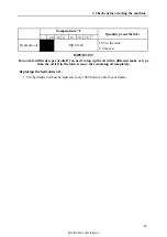
3 Recommended greases and fluids , page 108

2. Keep the battery charged. In cold weather, remove the battery after using the machine
and store it in a heated room to facilitate restarting the machine.

7.2 Starting in cold weather

WARNING

Consult these pages and respect these safety instructions before starting up the machine.

2.1 Precautions before starting the engine , page 43

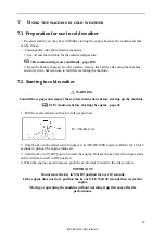
1. Pull the acceleration lever back to full gas position.

B= Throttle lever

2. Turn the key in the starter switch to place it in AIR HEATER position. Hold it for 10 to15
seconds to preheat the engine intake air.

3. Turn the key to START position to start the engine. Release the key after the engine starts
and it will return itself to ON position.

4. When the engine speed increases, push the accelerator forward to the idle position.

IMPORTANT

Do not leave the key in START position for over 10 seconds.

If the engine does not start, position the key at OFF. Wait 30 seconds then restart the

engine.

Moving or operating the machine without warming it up first may affect its

performance.

67

[S2PU00027ZE02] [1204CsCshWbYs]

Summary of Contents for SK17SR

Page 1: ...U00027ZE02 APPLICABLE No SK17SR 5 READ UNDERSTAND AND FOLLOW ALL SAFETY PRECAUTIONS AND INSTRUCTIONS FOUND IN THIS MANUAL BEFORE OPERATING THE MACHINE 2015 11 EU PU10 20000 MUB42ENMA00102 S2PU00027ZE0...

Page 2: ...S2PU00027ZE02 1204CsCshWbYs...

Page 3: ...ts perfomances beyond the original factory specifications the warranty expires and the improvements on site under warranty are rejected The use of fuel beyond the specifications required or boosting t...

Page 4: ...S2PU00027ZE02 1204CsCshWbYs...

Page 5: ...sentative authorised to compile the technical file 2000 14 EC Noise emission 2 EN 474 1 2006 A4 2013 EN 474 5 2006 A3 2013 EC DECLARATION OF CONFORMITY 2 1 Conformity assessment procedure followed 2 2...

Page 6: ...S2PU00027ZE02 1204CsCshWbYs...

Page 7: ...on about your KOBELCO machine here Always use these references for everything to do with your KOBELCO machine Model name Machine serial number Serial number of the engine Your KOBELCO dealer Address T...

Page 8: ...S2PU00027ZE02 1204CsCshWbYs...

Page 9: ...rget to pass on the manual at the same time KOBELCO provides its customers with products that conform to the regulations and indus trial standards that apply in their respective countries If you are u...

Page 10: ...S2PU00027ZE02 1204CsCshWbYs...

Page 11: ...his machine must be competent and trained in its use WARNING Never try to operate or repair the machine if you have not read and understood all the ap plicable warnings and usage instructions containe...

Page 12: ...temperature indicator 14 5 1 3 Engine oil pressure alert indicator 14 5 1 4 Battery charge warning alert 15 5 1 5 Water temperature alarm light 15 5 1 6 Preheating light 15 5 1 7 Time counter 16 5 1 8...

Page 13: ...l parts and tools 42 2 Usage precautions 43 2 1 Precautions before starting the engine 43 2 1 1 Make sure that your workplace is safe 43 2 1 2 Clean the machine 43 2 1 3 Check the safety structures 44...

Page 14: ...t 76 9 4 Digging trenches 76 9 5 Loading 76 10 Handling of accessories 77 10 1 Hydraulic hammer SOCOMEC 77 11 Accessory change by direct coupling 79 11 1 Dismantling the accessory 79 11 2 Mounting the...

Page 15: ...st 50 hours of service 107 4 2 After the first 250hours of service 107 5 List of periodic inspections and maintenance operations 108 6 Maintenance by the operator 111 6 1 Daily maintenance 111 6 1 1 C...

Page 16: ...oning 127 E Technical data 129 1 Specifications 131 2 Working dimensions 132 3 Noise emitted by the machine 133 4 Vibrations emitted by the machine 134 Appendices 139 A Control sheets to be photocopie...

Page 17: ...the machine CHAPTERS COVERED IN THIS PART 1 APPLICATIONS AND REGULATIONS 2 IDENTIFICATION PLATES 3 WARNING LABELS 4 IDENTIFICATION OF IMPORTANT PARTS 5 DESCRIPTION OF THE DRIVING POSITION 6 COVERS 7...

Page 18: ...2 S2PU00027ZE02 1204CsCshWbYs...

Page 19: ...ne must not be used for any tasks that are not covered CAUTION It is forbidden to transport or lift people with the machine 1 2 Warranty Refer to the maintenance book 1 3 Driving permits Before using...

Page 20: ...equipped with a standard bucket and tanks topped off 5 Weight of the machine with operator 75 kg 6 Serial number and engine power 7 Machine serial number 2 2 Engine serial number plate The engine s se...

Page 21: ...n request When you order spare parts or call for an inerven tion tell your dealer the model name the serial number of the machine and the serial number of the engine and the number of hours displayed...

Page 22: ...the correct location and are legible If an adhesive label is missing damaged or illegible replace it straight away In the same way if an adhesive label is on a part that has been replaced add a new ad...

Page 23: ...3 Warning labels 7 S2PU00027ZE02 1204CsCshWbYs...

Page 24: ...e precautions page 43 4 Do not remove the protective casings while the machine is running 2 2 9 Radiator ventilator page 106 5 Pressurised elements Do not unscrew while the liquid is hot 1 8 Avoid rem...

Page 25: ...116 14 This sticker describes the operation of the machine controls and their location relative to the operator seat 5 3 Joysticks and pedals page 19 15 Always fasten your safety belt and adjust it be...

Page 26: ...d upkeeps page 101 6 1 5 Greasing points page 114 20 Use this pedal to command the accessory 5 3 8 P T O pedal page 24 21 Before starting the machine transportation check the total height of the load...

Page 27: ...ade 2 Boom cylinder 3 Bucket 4 Axes 5 Bucket link 6 Arm 7 Bucket cylinder 8 Arm cylinder 9 Boom 10 Blade cylinder 11 Throttle lever 12 Locking lever 13 Sprocket wheel 14 Track roller 15 Idle wheel 16...

Page 28: ...speed pedal 5 P T O pedal 6 Foot rest 7 Side movement pedals 8 Foot rest 9 Boom rotation pedal 10 Locking lever 11 Horn 12 Right command lever 13 Blade lever 14 Headlight switch 15 Control panel 16 St...

Page 29: ...s blown Only the water temperature alarm light goes off after a few seconds All the lights go off after the engine is started If a problem occurs when starting a light comes on and the alarm sounds WA...

Page 30: ...temperature indicator C cold H hot It indicates the temperature of the engine cooling fluid The normal temperature is close to zone 1 dur ing normal operation If the temperature of this coolant reach...

Page 31: ...s later If the temperature rises abnormally during opera tion the light comes on and the alarm sounds indicat ing that the engine is overheating 1 Slow the engine for a while then shut it down 2 When...

Page 32: ...maintenance operations When the engine is running the time counter per manently records the time even if the machine is not being used The time counter records 1 for one hour without considering the e...

Page 33: ...5 Description of the driving position 17 5 2 Switches 1 Start key 2 Headlight switch 3 Horn S2PU00027ZE02 1204CsCshWbYs...

Page 34: ...RT position to start the engine Re lease the key after the engine starts and it will return it self to ON position AIR HEATER position pre heating Turn the key to AIR HEATER position to warm up the ai...

Page 35: ...pedals 1 Locking lever 2 Left command lever c 3 Right command lever 4 Travel levers and pedals 5 Throttle lever 6 Blade lever 7 P T O pedal 8 Boom rotation pedal 9 Protection of pedals 10 2nd speed pe...

Page 36: ...ovement cannot be activated even though the right and left hand command levers may be moved WARNING Place the locking lever s in locked position as soon as you leave the seat WARNING The movement rela...

Page 37: ...e of the machine may cause serious injury or even death Personnel involved in using and maintaining the machine must familiarise themselves with the content of this manual before carrying out a task W...

Page 38: ...stopped 1 Position the travel levers in the neutral position 2 Push the right travel lever to rotate forward or pull the right travel lever to turn backwards To turn right do the same thing with the l...

Page 39: ...NG The blade movement is not secured by the locking lever even when the latter is in the loc ked position Do not operate the blade lever when you are not using it 5 3 7 Protection of pedals The P T O...

Page 40: ...om to the left or right a Rotate right press right b Rotate left press left n If the pedal is released it returns to the neutral posi tion and the boom keeps its position 5 3 10 2nd speed pedal Press...

Page 41: ...oncrete stuck to the track spacing change system may cause an abnormal operation If mud sticks to the moving parts of the track spacing change system make it work by spreading and then close up the tr...

Page 42: ...an operate the controls easily and comfortably WARNING Do not adjust the seat position when you are working on the machine adjust it before you start Always fasten your safety belt and adjust it befor...

Page 43: ...uipment and the electrical cabling against a surge In case of a bad contact or if the electrical system does not work when the key is on replace the faulty fuse with a fuse in good condition 6 3 1 Fus...

Page 44: ...uel supply pump Timer B 15A Boom headlamp Horn High speed valve C 15A Dashboard Cut off valve Safety relay Movement alarm D 15A Spare fuses 5 8 Headlights WARNING The headlight becomes very hot when i...

Page 45: ...temperatures are brought back down Opening the cover 1 Insert the starter key into the lock 2 Turn the key anti clockwise 3 Pull the handle to unlock the safety mechanism The cover opens 4 Lock the co...

Page 46: ...the cover 1 Insert the starter key into the lock 2 2 Turn the key anti clockwise Closing the cover 1 Close the cover 1 2 Press on it until you hear a click 3 Turn the key clockwise to activate the loc...

Page 47: ...it push the lid un til it locks 7 2 Antistarter mechanism with keypad 31 1 Once the user code has been programmed type A and the 4 digits of the code directly and confirm with the V button Note When t...

Page 48: ...nds after the contact key is turned to OFF 7 4 Quick hitch CAUTION Before any connection or disconnection of the hydraulic hoses remove the residual pres sure from the hydraulic circuit 2 1 1 Removing...

Page 49: ...cket or accessory is compatible with the capabilities of your machine 9 2 Compatible accessories page 75 the bucket or accessory mounting operation is performed on a level and stable ground the bucket...

Page 50: ...y 5 Remove the key and store it 6 Manoeuvre the arm to disengage the tool s quick hitch Mounting the accessory 1 Place the accessory on a stable flat surface 2 Clean all the parts 3 Place the arm equi...

Page 51: ...the quick hitch from the bucket or accessory Mounting the accessory 1 Place the accessory on a stable flat surface 2 Clean all the parts Note Make sure the locking pins are retracted into the quick h...

Page 52: ...36 S2PU00027ZE02 1204CsCshWbYs...

Page 53: ...NE 5 CHECKS AFTER START UP 6 CHECKS AFTER USE 7 USING THE MACHINE IN COLD WEATHER 8 RUBBER TRACKS 9 HANDLING THE BUCKET 10 HANDLING OF ACCESSORIES 11 ACCESSORY CHANGE BY DIRECT COUPLING 12 IMPLEMENTIN...

Page 54: ...38 S2PU00027ZE02 1204CsCshWbYs...

Page 55: ...safety mechanisms in place Make sure that all covers and all housings are properly installed in their respective posi tions If any of them are damaged repair them immediately The use of safety mechani...

Page 56: ...enclosed space open the windows and doors to let air circulate Never let the engine idle unnecessarily and never leave the engine running when you are not using the machine Provide respirators based o...

Page 57: ...il must be stored in a place that re sponds to applicable safety regulations Unauthorised personnel must not enter this area 1 8 Avoid removing the caps when the temperatures are high The engine coola...

Page 58: ...KOBELCO Product Warranty the applicable warranty would also become null and void If you want to modify your machine you must contact your dealer 1 12 Precautions for optional parts and tools Any modi...

Page 59: ...ound the engine may catch fire Clean these materials from the machine Dirt oil and snow on the cab floor the levers handles or steps are slippy and dangerous Clean them completely Proceed to the check...

Page 60: ...tures mounted on the machine comply with the recommendations of ROPS ISO 3471 FOPS ISO 3449 For the specifications of these structures refer to the table below Type ROPS TOPS Weight in conformity with...

Page 61: ...r the track is dirty or covered with oil wash them off 2 1 6 Fasten your safety belt and adjust the rearview mirror s The operator s seat is fitted with a safety belt Always fasten your safety belt an...

Page 62: ...nearby using the horn or any other si gnal before starting the machine DANGER If a person is in the machine s danger zone it may be struck by the machine s moving parts or be wedged between the machin...

Page 63: ...e machine may lose its balance and tip over when rotating the upper part or when the equipment is working on a slope Do not pivot the upper structure with a load in the bucket If the rotation cannot b...

Page 64: ...the ground with the bucket s teeth in contact with the ground This may apply excessive force to the rear of the machine and shorten its life span Do not use the hydraulic cylinder to the end of its r...

Page 65: ...make sure that the bucket and blade do not come into contact Support the blade on both sides When you use the blade as a support press the blade down on both sides Pay attention to the blade during e...

Page 66: ...n the work site contact the electricity production company concerned Voltage V Minimum safety distance m Transformer 100 200 2 6600 2 Transmission line 22000 3 66000 4 154000 5 275000 7 2 3 4 Working...

Page 67: ...oads are dangerous as the machine may slip even on a slight incline Drive the machine at reduced speed do not stop or turn suddenly Remove the snow carefully as verges or other potential dangers may b...

Page 68: ...r if the machine is climbing a slope with an angle of over 15 there is a risk that the rear of the upper struc ture will remain submerged in the water which risks damaging the radiator when it stirs u...

Page 69: ...owing procedures If only one track is stuck 1 Place the bucket on the muddy side 2 Lift the track 3 Place wood or a wedge under the track runners 4 Raise the bucket IMPORTANT When you raise the machin...

Page 70: ...top it immediately Reduce the engine temperature progressively by running it at an intermediate rotation speed before stopping it 3 Lower the bucket to place its lower surface in contact with the grou...

Page 71: ...inertia of the upper struc ture will increase and continue to rotate over a long distance once the rotation lever has been released This may give the operator a false impression of the distance to be...

Page 72: ...battery away from all flames and sparks If you accidentally swallow any of the battery s electrolyte drink a large quantity of water milk or fresh eggs and consult a doctor immediately Before inspect...

Page 73: ...erwise there is a risk that its performance will be affected and its life span shortened When running in the machine make sure to Preheat the engine by running it on idle for 5 minutes after starting...

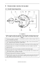
Page 74: ...ator 3 Check that there are no oil leaks from the engine or water leaks from the cooling system 4 Check that there are no oil leaks from the hydraulic system the hydraulic oil tank the pipes and seals...

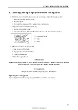
Page 75: ...id in the tank is between the min and max markers A expansion flask 1 maxi 2 mini If the level is below the min marker 1 Take the cap off the tank 2 Top up to the maximum marker 3 Close the tank again...

Page 76: ...hole If the oil level is above marker H remove the ex cess quantity of oil via the drainage cap P then check the level again Note Do not pour the excess engine oil onto the ground or the road Once th...

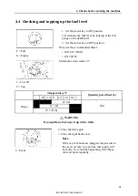
Page 77: ...iesel ISO 8217 DMX EN 590 96 Minimum cetane index 45 1 Cover R 2 Cap Temperatures C Quantity prescribed L 20 10 0 10 20 30 Diesel N 2 D 20 0 N 3 D N 3 D S WARNING If you spill any fuel wipe it up with...

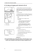
Page 78: ...e central point of the gauge scale oil temperature 10 to 30 C During normal operation the oil level must be around the upper limit marker on the oil gauge scale oil temperature 50 to 80 C 4 If the oil...

Page 79: ...tact your dealer Temperatures C Quantity prescribed L 20 10 0 10 20 30 Hydraulic oil ISO VG46 16 5 in the tank 9 5 the rest IMPORTANT Do not mix different types of oils If you need to top up the oil w...

Page 80: ...ine oil pressure alarm light is off 2 Check that the gauges and the screen correspond to the following statuses 1 Diesel gauge normal 2 Cooling fluid temperature indicator normal 3 Time counter normal...

Page 81: ...lever to ensure that no handling of the equipment and no rotation of the upper structure is possible with the joysticks 8 Unlock the locking lever and activate the joysticks to check that everything i...

Page 82: ...r the radiator vents are clogged Clean or replace the fuel filter cartridge regularly Clean the electrical equipment particularly the starter and the alternator to avoid any dust deposits If the machi...

Page 83: ...rting up the machine 2 1 Precautions before starting the engine page 43 1 Pull the acceleration lever back to full gas position B Throttle lever 2 Turn the key in the starter switch to place it in AIR...

Page 84: ...machine on these boards to avoid the tracks freezing on the ground 2 Drain the water built up in the fuel system by turning the evacuation tap to avoid and freezing 3 Cover the battery or place it in...

Page 85: ...tracks Use the rubber tracks moderately according to the conditions at the work site and the type of work 8 2 Rubber track warranty The rubber tracks are not guaranteed for repair and replacement if...

Page 86: ...ging the track Never rotate on ground with a significant difference in level Climb a step at a right angle to avoid the tracks coming off Gently lower a machine that has been raised from the ground wi...

Page 87: ...ence in level there is a spacing between the tracks and the rollers 1 Track 2 Tightener roller When you carry out side movement in reverse there is another spacing between the tension roller and the t...

Page 88: ...d according to the machine s stability limits the total weight of the quick hitch the accessories used bucket hydraulic hammer and the load handled does not exceed the maximum weight allowed The capab...

Page 89: ...ion is reminded by a sticker af fixed in the cab interior and visible from the driver s compartment Compare the result with the maximum weight under condition of use with bucket shovel or with accesso...

Page 90: ...monly handled materials Weight of material handled The bucket loading capacity or SAE volume allows calculating the weight of material handled in the bucket in case of full buckets and it takes into a...

Page 91: ...se serious physical injuries and ex tensive material damage 9 1 Machine stability when using with a bucket or an accessory page 72 Do not use accessories that are not listed in this chapter The user m...

Page 92: ...bucket arm and the angle between the arm cylinder and the arm is 90 For maximum effectiveness handle the arm within the range illustrated opposite 45 forward and 30 back Do not move the equipment to...

Page 93: ...ing the hammer is finished set the hammer vertically with respect to the ground and leave it in this position to facilitate drainage of condensation on the side of the piston Tool change 1 Park the ma...

Page 94: ...ntil the pin stop returns to its position Note There are different forms of tools that can equip the hammer Contact your dealer If the hammer is inactive for a long period you must Pull out the tool a...

Page 95: ...e accessory at about 5 cm above the ground 3 Stop the engine 4 Clean all the parts 5 Remove the swivel pin from the A bore and the swivel pin from the B bore IMPORTANT Protect the various elements fro...

Page 96: ...ket or accessory is compatible with the capabilities of your machine the bucket or accessory mounting operation is performed on a level and stable ground the bucket or accessory is properly positioned...

Page 97: ...the equipment and align the arm bore with the bucket B bore holding the bucket about 5 cm of the ground Add shims to compensate for play if necessary 6 Insert the swivel pin into bore B 7 Put the bol...

Page 98: ...TION Do not operate the controls of the 3rd circuit if there are no installed accessories 12 1 1 3rd circuit selector Use this valve located near the battery to select the single or double acting 3rd...

Page 99: ...ressure page 103 Always drain the machine s oil into a safe container and never directly onto the ground 1 Stop the engine 2 Remove the caps 3 Connect the hydraulic tool s hoses Hydraulic oil rate at...

Page 100: ...s are sufficiently wide long and thick to hold the machine so that you can load it and unload it safely If the ramps flex excessively consolidate them with wedges Install the ramp safely on the truck...

Page 101: ...nd load the machine onto the truck Do not use levers other than the side movement levers when travelling across the ramp plates 13 2 Immobilising the machine on the truck Once the machine is in a suit...

Page 102: ...nsport vehicle surface If the surface is greasy it must be cleaned before installing the machine on the transport vehicle Note If the transport vehicle surface is steel provide a non slip mat or space...

Page 103: ...gitudinal axis of the machine 4 Place all the equipment cylinders to maximum extension except the rotation cylinder 5 Stop the engine put the levers in the locked position and check that you have left...

Page 104: ...13 Transporting the machine 88 Length m C M U 2 t C 2 m 2 D 4 m x 2 2 2 Working Load Limit WLL S2PU00027ZE02 1204CsCshWbYs...

Page 105: ...the side movement motor If during cold weather the hydraulic oil temperature rises to over 60 C in relation to the exte rior temperature during an unloading operation without movement after the engin...

Page 106: ...The starter works correctly but the engine does not start Lack of fuel Top up the fuel tank Air in the fuel circuit Repair the air leak Evacuate the air from the fuel circuit Defective fuel injection...

Page 107: ...ective battery Replace the battery The starter speed is too low Defective electric circuit Check and replace the electric circuit Battery insufficiently charged Recharge the battery Defective starter...

Page 108: ...ly The rotation brake is not unlocked Unlock the rotation locking lever Insufficient quantity of grease Check and lubricate Defective rotation brake valve Check and repair Defective rotation motor Che...

Page 109: ...isconnect them start with the negative terminal mass If a tool comes into contact with the machine s positive terminal there is a risk of sparks Do not connect the connection cables to the terminals i...

Page 110: ...engine speed to maximum 3 Turn the starter switch of the machine that has broken down to START to start the engine If the engine does not start wait at least two minutes before trying again Do not st...

Page 111: ...ation as soon as the battery is charged If you continue the follow ing faults may occur battery overload reduction in the battery electrolyte battery failure The battery must only be handled once the...

Page 112: ...in the mud and can not get out on its own or when it is towing a heavy object attach the sling as shown opposite 1 Shackles 2 Slings Minimum capacities of the coupling devices to use W L L 3 t Shackle...

Page 113: ...ART 1 PERIODIC INSPECTIONS AND UPKEEPS 2 MAINTENANCE PRECAUTIONS 3 RECOMMENDED GREASES AND FLUIDS 4 FIRST MAINTENANCE 5 LIST OF PERIODIC INSPECTIONS AND MAINTENANCE OPERATIONS 6 MAINTENANCE BY THE OPE...

Page 114: ...98 S2PU00027ZE02 1204CsCshWbYs...

Page 115: ...c oil return filter 1st time Operation of the accumulator Greasing Greasing points Rotation pin and crown Track spacing piston Chassis Bearing rollers and bearings idler wheels Track tension Electrica...

Page 116: ...odic inspections and upkeeps 100 Scheduled maintenance points of the machine lubrication filters Hydraulic oil Engine oil Hydraulic oil return filter Travel gears Greasing points S2PU00027ZE02 1204CsC...

Page 117: ...Boom Bucket Blade lever 3rd hydraulic circuit control P T O 1 4 Stop the engine by turning the key from ON position to OFF position 5 Remove the key from the ignition The residual pressure in the accu...

Page 118: ...characteristics of the machine components These products may also deteriorate the rigidity of the tank Do not spill any water onto the dashboard Do not spray water directly at high pressure onto the...

Page 119: ...2 2 4 Dismantling the accessory If the scheduled task requires the dismantling of the accessory remove it carefully by following the in structions described in this manual 11 1 Dismantling the accesso...

Page 120: ...rrent when working on the electrical circuit repair welding 2 2 8 Hoses Do not fold the high pressure hoses Do not strike them against any hard objects Damaged or incorrectly bent hoses pipes and duct...

Page 121: ...e sure there are no seals or bearings between the soldered part and the earthed part Do not earth near the axes of the equipment or the hydraulic cylinder 2 2 11 Waste processing Always drain the mach...

Page 122: ...TANT Do not mix different types of oils If you need to top up the oil with a different make or type from the oil left in the tank remove the remaining oil completely Components Fluid Temperatures C Qu...

Page 123: ...nt replaced Greasing the pin and rotation crown Greasing the track spacing piston Replace the hydraulic fluid return filter element Contact your dealer 4 2 After the first 250hours of service Replace...

Page 124: ...uencies for examplen the operations to be carried out every 50 hours must be carried out at 50h 100h 150h 200h etc Certain intervals may vary if a hydraulic hammer is used Refer to the corresponding n...

Page 125: ...hoses 6 1 8 Checking the hydraulic hoses page 116 Fuel hoses 6 1 9 Visual inspection of the fuel hoses page 116 Fuel tank 4 4 Checking and topping up the fuel level page 61 Engine oil Cooling fluid 4...

Page 126: ...ent Fuel injection valve Verification and adjustment Cylinder head block Bolt re tightening Fuel pump Check Control filters Replacement Bearing rollers and bearings idler wheels Greasing Every 2000h I...

Page 127: ...eadlights the alarm and the lights are working correctly If an element is not working or you think it is defective shut down the machine s engine immediately and contact your dealer If a headlight bul...

Page 128: ...machine or after use in the rain on soft ground or in muddy water Proceed as follows 1 Lower the bucket and the blade to the ground 2 Stop the engine 3 Clean the greasing connectors indicated by the a...

Page 129: ...1 Open the rear bonnet 2 Place a container under the separator 3 Close the purge tap A Fuel filter B Decanter separator 4 Loosen the bowl tightening ring 1 Tightening ring 2 Element 3 Ring 5 Remove th...

Page 130: ...eaks from the hydraulic hose connectors 6 1 9 Visual inspection of the fuel hoses Visually check that the fuel does not leak from the fuel hose connectors Also check that the hoses are not damaged If...

Page 131: ...move the lid from the fusebox 3 Identify the burnt out fuse 4 Replace it with an equivalent fuse Fuse strip General supply fuses IMPORTANT An unsuitable fuse or a fuse holder with a short circuit may...

Page 132: ...6 4 Rubber track maintenance 6 4 1 Checking the condition of the tracks The wear to the rubber tracks depends on the working conditions and the nature of the ground Regularly check the wear and tensi...

Page 133: ...chment in serts repair it if the length of the crack reaches 60 mm If the interior steel cable is exposed repair the track immediately even if the crack is a small one If the length of the crack is le...

Page 134: ...e tension The play H between the external rolling surface of the second track roller on the tightener rooler and the internal surface of the track must be 8 13 mm 1 Greaser b Track roller c Track If t...

Page 135: ...er c Track 5 Proceed with the track tensioning To check that the tension is correct put the machine down and move it gently forwards and back 6 Check the tension again If it is still not correct ad ju...

Page 136: ...the cover IMPORTANT The rubber track does not resist grease Wipe the grease off completely as it may reduce the life time of the rubber tracks 6 4 5 Releasing the tension WARNING Do not loosen the gre...

Page 137: ...l pump Check Battery electrolyte Density check Cylinder head block Bolt re tightening Every 2000h Fuel hose coolant hose Verification and replacement Injectors and injection pressure Inspection and ca...

Page 138: ...122 S2PU00027ZE02 1204CsCshWbYs...

Page 139: ...The conservation and storage of the machine must comply with standard NF ISO 6749 Earth moving equipment conservation and storage of October 1987 The following chapters take part of the standard menti...

Page 140: ...124 S2PU00027ZE02 1204CsCshWbYs...

Page 141: ...e characteristics and is appropriate for the machine s storage temperatures 3 Recommended greases and fluids page 108 If necessary top up the water 4 2 Checking and topping up the level of cooling flu...

Page 142: ...oning instructions as well as the conservation date must be placed in an impermeable envelope with a label and secured to the machine at a visible location To protect the machine against rainwater tra...

Page 143: ...ing order Before using the machine again after a storage period of two months do the following 1 Remove the protections on the hydraulic cylinder rods 2 Apply a large quantity of oil or grease to the...

Page 144: ...128 S2PU00027ZE02 1204CsCshWbYs...

Page 145: ...129 E Technical data CHAPTERS COVERED IN THIS PART 1 SPECIFICATIONS 2 WORKING DIMENSIONS 3 NOISE EMITTED BY THE MACHINE 4 VIBRATIONS EMITTED BY THE MACHINE S2PU00027ZE02 1204CsCshWbYs...

Page 146: ...130 S2PU00027ZE02 1204CsCshWbYs...

Page 147: ...m mm 1535 1380 Boom rotation angle left right 42 65 Maximum excavation force bucket arm kN 15 2 Travel Speed high low km h 4 3 2 1 Maximum slope 30 Rotation speed rpm 9 5 Average pressure on the groun...

Page 148: ...0 B 450 R 3810 C 640 S 2310 D 2505 85 T 1025 E 2905 125 U 1850 F 1280 V 2200 G 640 Y 2630 H swing 1535 1380 Z 3690 I 260 AA 175 K Canopy 2300 AB 230 L 205 AC 10505 720 N 1525 AD 12805 950 O 3450 5 Tra...

Page 149: ...pressure measured with frequency weighting C Measurements carried out machine in static position machine running at nominal power LwA determined and guaranteed according to Directive 2000 14 CE amend...

Page 150: ...he gravel storage area approximate speed 4km h 2 6 mi h clockwise turn Hydraulic hammer Operation of hydraulic rock breaker for 20 seconds on a steel plate of 100x50x5cm placed on the ground Note Thes...

Page 151: ...Appendices Additional informations A Control sheets to be photocopied B Notes C Lashing record 135 S2PU00027ZE02 1204CsCshWbYs...

Page 152: ...track spacing pis ton page 117 Control sheet Maintenance every 50 hours Number of hours of service hours Parts Operations Done by the Rotation pin and crown Greasing 6 2 1 Greasing the pin and rotatio...

Page 153: ...cceleration levers Verification and adjustment Dealer Air filter 5 Cleaning GO filter Replacement Control sheet Maintenance every 250 hours Number of hours of service hours Parts Operations Done by th...

Page 154: ...ion pin and crown Greasing Track spacing piston Greasing Engine oil Replacement Oil filter Replacement Dealer Radiator vents Cleaning Side movement and acceleration levers Verification and adjustment...

Page 155: ...ment Aspiration filter Cleaning or replacement depend ing on the filter Dealer Radiator vents Cleaning Belt Replacement Side movement and acceleration levers Verification and adjustment Air filter Rep...

Page 156: ...ment Aspiration filter Cleaning or replacement depend ing on the filter Dealer Radiator vents Cleaning Belt Replacement Side movement and acceleration levers Verification and adjustment Air filter Rep...

Page 157: ...s Cleaning Dealer Belt Replacement Side movement and acceleration levers Verification and adjustment Hydraulic oil return filter Replacement Battery electrolyte Density check GO filter Replacement Coo...

Page 158: ...142 S2PU00027ZE02 1204CsCshWbYs...

Page 159: ...B Notes 143 S2PU00027ZE02 1204CsCshWbYs...
Page 160: ...ories from relaxing during transport 3 Check the location and condition of the machine tie down points 4 Tie down the machine at the points provided for that purpose and that are indicated on the mach...

Page 161: ...nservation 127 Cover B 30 Covers 29 D Daily maintenance 113 Dashboard 13 Detecting anomalies 91 Diesel type 108 Diesel gauge 14 Dismantling Accessories 80 Driver s seat 26 Driving the machine on a slo...

Page 162: ...Quick hitch 32 R Recommissioning 129 Rubber track maintenance 118 Rubber tracks 69 Running in 57 S Safety signals xi Soldering 107 Specifications 133 Start key 17 Stopping the engine 53 Storage 128 T...

Reviews: