USER MANUAL CENTRAL HEATING STATION TYPE C32SPV24MEC; C32SPV31MEC
REV.12.06.2017
16 of 18
11.2
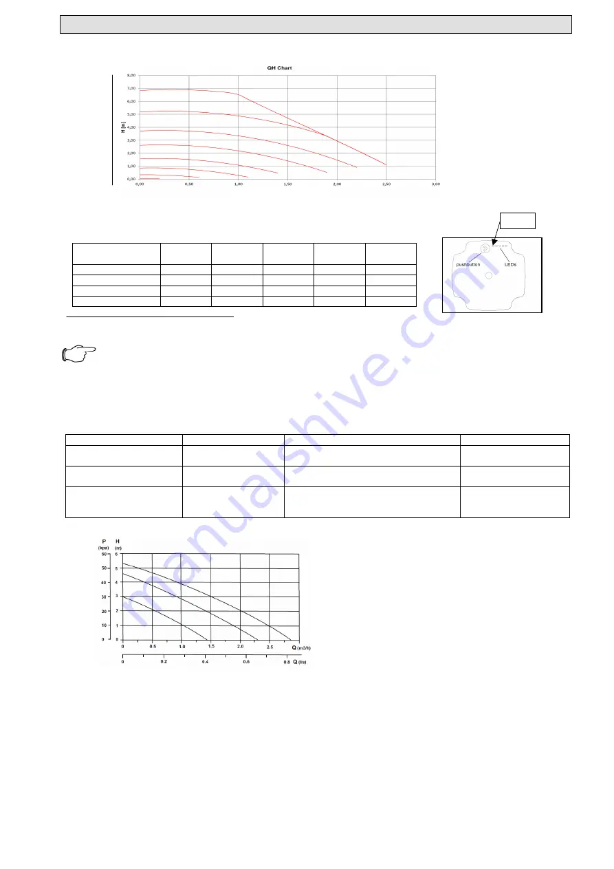
Hydraulic characteristic of ER P pump (EEI≤0,2)
When designing the thermal installation, the hydraulic characteristics of the pump need to be taken into consideration.
Pump settings:
The pump can be set to function in four modes (4 steps).
Table 6 – Pump functioning modes
UPM3 Flex As
[m]
LED 1
red
LED 2
yellow
LED 3
yellow
LED 4
yellow
LED 5
yellow
4
•
•
5*
•
•
•
6
•
•
•
•
7*
•
•
•
(*)functioning mode set in the factory.
To set on another curve please contact the authorized service company.
NOTE!
To save on energy and to maintain the possible functioning noises to a low level, please choose a low characteristic
curve.
Pump error codes
If the pump has detecte one or more errors, the bi-colour LED 1 changes from green to red. When an error is active, LEDs
indicate the type of error as presented in table 7.
If more alarms are active at the same time, LEDs show the rror with the highest priority.
Tab. 7 Pump error codes
11.3
Hydraulic characteristic of non-ER P pump
Q PUMP FLOW [mc/h]
Display
Meaning
Pump action
Repair
1 LED red + 1 LED yellow
(LEDl 5)
Blocked rotor
Pump tries to restart every 1.5 seconds
Wait or deblock the
engine shaft
1 LED red + 1 LED yellow
(LEDl 4)
Feeding voltage too
low
Only warning, the pump functions
Check the feeding
voltage
1 LED red + 1 LED yellow
(LEDl 3)
Electrical error
Pump is stopped because the feeding
volatage is too low or feeding is
incorrect
Check the feeding
voltage / replace the
pump
P
U
M
P
P
R
E
S
S
U
R
E
[k
p
a
]
80
70
60
50
40
30
20
Q PUMP FLOW [mc/h]
LED 1
P
P
U
M
P
P
R
E
S
S
U
R
E
[m
c
a
]


