background image

14/14 

November

 / 2006


FACTORY AUTHORIZED SERVICE       
Thorne Electric Company 
610 Lanark Suite  205 
San Antonio TX ,78218 
Tel (210) 590-1226 
Fax (210) 590-1258 
1-800-548-5741 


FACTORY  
Koblenz Electrica ,S.A. de C.V. 
Av. . Ciencia No 28 Cuautitlán Izcalli  
Edo. de México ,C.P. 54730 
Tel : 5864-0300 
Web site : 

http://www.koblenz.electric.com


KOBLENZ ELECTRICA S.A. DE C.V. 
E-mail: servicio@koblenz-electric.com 


LP-P1800-200611 


 S

E

R

V

IC

E


To Order Parts Call 1-888-702-5326 - https://monsterfloorequipmentparts.com

Summary of Contents for P-1800

Page 1: ... P 2600 KOBLENZ ELECTRICA S A DE C V E mail thorne_scsm koblenz electric com NOVEMBER 06 LP P1800 200611 SERVICE SERVICE MANUAL PARTS LIST T o O r d e r P a r t s C a l l 1 8 8 8 7 0 2 5 3 2 6 h t t p s m o n s t e r f l o o r e q u i p m e n t p a r t s c o m ...

Page 2: ...G CHART 6 IV ELECTRICAL RATING 7 V WIRING DIAGRAM 8 VI SCHEMATIC EXTERNAL MACHINE PARTS 9 VII EXTERNAL MACHINE PARTS LIST 10 VIII SCHEMATIC INTERNAL PARTS 12 IX INTERNAL MACHINE PARTS LIST 13 T o O r d e r P a r t s C a l l 1 8 8 8 7 0 2 5 3 2 6 h t t p s m o n s t e r f l o o r e q u i p m e n t p a r t s c o m ...

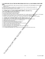
Page 3: ...ower cord plug and touch other probe to handle tube There should be no breakdown RUNNING RUN THE MACHINE WITHOUT BRUSHES FREE RUNNING AND CHECK A There should be no unusual noise or vibration B The carbon brushes spark should be small and uniform C The current shall bi no more than 1 5 A D Run the machine with scrubbing brushes on the floor the current shall be 3 0 A T o O r d e r P a r t s C a l ...

Page 4: ... the fan end of the unit measured by a feeler gage 2 10 Replace the cover plates gaskets and screws 84 85 86 and 61 2 11 place the block 75i n the detent connector 75 and push close the connector on motor cable 24 2 12 Place the unit into the cover 35 and secure with the four cover screws 93 2 13 Reconnect the elbow hose connector 51 into the tray 95 3 TO REPLACE GEAR 77 OR 78 OR A SPINDLES 79 3 1...

Page 5: ...assembles 6 TO REPLACE 6 1 Remove four covers screws 93 and remove base plate 92 from the cover 35 6 2 Pull open the connector on motor cable 24 6 3 Remove the motor cable bushing 6 4 Remove the switch box retaining screw 6 6 5 Remove the switch box 5 from tube 2 6 6 Remove the switch cover screws 4 and open the cover 9 6 7 Disconnect the motor cable 24 from the switch 8 inserting a round needle o...

Page 6: ...t couple yellow turning it C W on the spindle while holding the other brush 10 5 Remove and replace the left couple black on similar way turning it C W to loosening and C C W to tighten 11 TO REPLACE A MOTOR FRAME 88 OR A BASE PLATE 92 11 1 Follow steps 1 1 1 2 1 3 3 2 32 3 3 5 3 6 3 7 and separate the base plate from the motor frame 11 2 Remove the screws 98 the washers 97 and the tray 95 11 3 Ba...

Page 7: ...brushes Replace carbon brushes A Broken or missing drive pin Replace drive pin 3 Cleaning Brush does not run B Gear failure Replace gear 4 Handle and yoke assembly does remain in up position A Worn or broken yoke spring Replace yoke spring 5 Cleaning brush does not lock on spindle cap A Defective spindle cap or brush retainer Replace spindle cap or retainer 6 Cleaning brush does not lock on coupli...

Page 8: ...8 14 November 2006 IV ELECTRICAL RATING V A Hz 120 4 2 50 60 V WIRING DIAGRAM T o O r d e r P a r t s C a l l 1 8 8 8 7 0 2 5 3 2 6 h t t p s m o n s t e r f l o o r e q u i p m e n t p a r t s c o m ...

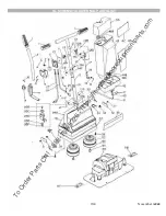
Page 9: ...9 14 November 2006 VI SCHEMATIC EXTERNAL PARTS LIST T o O r d e r P a r t s C a l l 1 8 8 8 7 0 2 5 3 2 6 h t t p s m o n s t e r f l o o r e q u i p m e n t p a r t s c o m ...

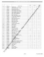
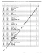
Page 10: ...RAL PIN 3 32 1 1 12 C 24 0158 6 VALVE SPRING 1 12 C 24 0098 4 VALVE SPRING 1 12 D 06 0464 5 DISPENSER 1 12 D 06 0868 7 DISPENSER PAINTED 1 13 05 0482 9 CHROME CORD HOOK 2 14 03 0208 3 RIVET 5 32 X 1 4 2 16 01 0062 8 SELF TAPPING SCREW 6 20 1 1 17 09 0811 1 DISPENSING ROD 1 1 18 05 2197 1 VALVE HOOK 1 1 19 05 2223 5 VALVE HOOK SPACER 1 1 21 45 0330 6 HANDLE SCREW NUT PACKAGE 2 2 2 21 A 01 0747 4 SC...

Page 11: ...MBLY 1 41 45 0140 9 144 OZ TANK ASSEMBLY 1 41 A 13 0064 9 TANK CAP 1 1 41 B 04 0136 4 WASHER VALVE SPRING CUP 1 1 41 C 13 0068 0 VALVE CAP 1 1 42 17 2004 4 TANK TOP LABEL 1 43 17 2042 4 TANK LABEL 1 43 17 4089 3 TANK LABEL 1 46 13 0948 6 CONTAINER BASE BLACK 1 46 13 2588 5 CONTAINER BASE BLUE 1 47 01 1093 2 SELF TAPPING SCREW 2 2 48 12 0694 5 CONTAINER BASE SEAL 1 1 50 13 0076 3 HOSE 1 1 51 13 006...

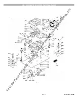
Page 12: ...12 14 November 2006 VIII SCHEMATIC MACHINE INTERNAL PARTS T o O r d e r P a r t s C a l l 1 8 8 8 7 0 2 5 3 2 6 h t t p s m o n s t e r f l o o r e q u i p m e n t p a r t s c o m ...

Page 13: ...8 3 GEAR SPINDLE KEY 2 2 2 81 04 0018 4 WASHER 500 X 685 4 4 4 82 04 0238 8 SPINDLE RETAINER 2 2 2 83 13 1956 5 FRAME INSULATOR 2 2 2 84 23 0462 4 GEAR CASE COVER 1 1 1 85 23 0461 6 GEAR CASE COVER 1 1 1 86 37 0133 1 GASKET GEAR COVER 2 2 2 87 05 2718 4 SUPPORT 3 SPEED BLOCKS 1 1 1 88 23 0330 3 MOTOR FRAME ASSEMBLY 1 1 1 89 13 0059 9 FRAME SPACER 1 1 1 90 13 1040 8 MOTOR SUPPORT 3 3 3 91 13 0758 6...

Page 14: ... FACTORY Koblenz Electrica S A de C V Av Ciencia No 28 Cuautitlán Izcalli Edo de México C P 54730 Tel 5864 0300 Web site http www koblenz electric com KOBLENZ ELECTRICA S A DE C V E mail servicio koblenz electric com LP P1800 200611 SERVICE T o O r d e r P a r t s C a l l 1 8 8 8 7 0 2 5 3 2 6 h t t p s m o n s t e r f l o o r e q u i p m e n t p a r t s c o m ...

Reviews: