6/14
November
/ 2006
9 .-TO REPLACE A FAULTY BRUSH SPINDLE INSULATOR ( 96 A ) ( ONLY MODELS WITH DRIVE
PINS )
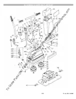
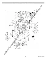
9.1.-Remove the spindle drive pin ( 96 D ) by driving it out with a cylindrical punch of suitable diameter and remove the pin
insulator ( 96 E )
9.2.-Remove the spindle cap insulator ( 96 A ) by pressing the tab ( 96 C ) and pulling the cap insulator out .
9.3.-Assemble the spindle insulator ( 96–E ) is aligned .
9.4.-Reassemble the brush drive pin so that equal it is exposed on either side of the spindle insulator ( 96 E )
10 .-TO REPLACE A 8 SLOTS BRUSH DRIVE COUPLE ( 106 OR 107 A )
( ONLY ON MODELS WITH 8 SLOT DRIVE )
10.1.-Turnt the machine with the brush side facing up.
10.2.-Insert a pair of brushes on the 8 slot couples.
10.3.-Hold the left brush ( black couple ) and turn the right brush C.C.W. until the couple unscrew and came out of the spindle
10.4.-Replace the new right couple ( yellow ) turning it C.W. on the spindle ,while holding the other brush .
10.5.-Remove and replace the left couple ( black ) on similar way turning it C.W. to loosening and C.C.W. to tighten.
11 .-TO REPLACE A MOTOR FRAME ( 88 OR A BASE PLATE ) ( 92 )
11.1.-Follow steps 1.1,1.2,1.3,3.2,32.3,3.5,3.6,3.7 and separate the base plate from the motor frame.
11.2.-Remove the screws ( 98 ) ,the washers ( 97 ) and the tray ( 95 ) .
11.3.-Base plate may now be replaced.
11.4.-To replace the motor frame ,follow steps 3.4,3.9,3.10,3.11.
11.5.-Remove four screws ( 64 ) and field supports ( 65-66 ) .
11.6.-Disconnect field wires from brush holder support ( 62 ) and remove it,
11.7.-Remove screws ( 68 ) and bearing clamps ( 69 ) .
11.8.-Remove push plates ( 73-74 ) and thrust balls ( 72 ) .
11.9.-Remove the field ( 67 ) and armature assembly ( 63 ) from the motor frame.
11.10.-The motor frame may now be replaced.
11.11.-For assembly of base plate ( 92 ) or motor frame ( 88 ) the steps are followed in reverse order.
To Order Parts Call 1-888-702-5326 - https://monsterfloorequipmentparts.com


