background image

ZED-Z 

page 18 


ZED-Z K11/0522 

USER CALIBRATION 

Menu Item


Function / Description 


CAL Freq

 
Calibrate by entering frequency and flow. 
 
In the menu item   

CAL Freq

  the bottom line always shows the current pulse value of the 

User calibration. 
 
Calibration process: 
 
a)  

 FlowVal 

  Enter nominal flow value of the sensor.  >  (e) press > 

 
b)  

 FlowUnit 

 Enter unit for flow value.  >   (e) press > 

 
c)  

 Freq.Val. 

Enter nominal frequency  >  finish with (e). 


The new pulse value of the User calibration is calculated from these three values and saved 
as user calibration for the flow measurement, e.g.  20.2757 pls./litre. 


CAL Vol. 


Calibration process using impulse counting and volume input (cc procedure). 
 
In the menu item   

CAL Vol.

  the bottom line always shows the current pulse value of the 

User calibration. 
 
Calibration process: 
 
a)  

 PulseCnt 

 measures number of impulses  

     (e) press  >  start counter  (impulses are counted)  >  (e) press >  stops counter. 
 
b)  

 Vol.Val 

 Enter measured volume value  >  (e) press.  

 
c)  

 Vol.Unit 

 Enter unit for volume value  >   finish with (e).  

 
The pulse value of the User calibration is calculated from these three values and is saved 
as the user calibration for the flow measurement, e.g.  3900,5 pls./L. 


*) CAL Freq  – Only possible with ZED devices. 


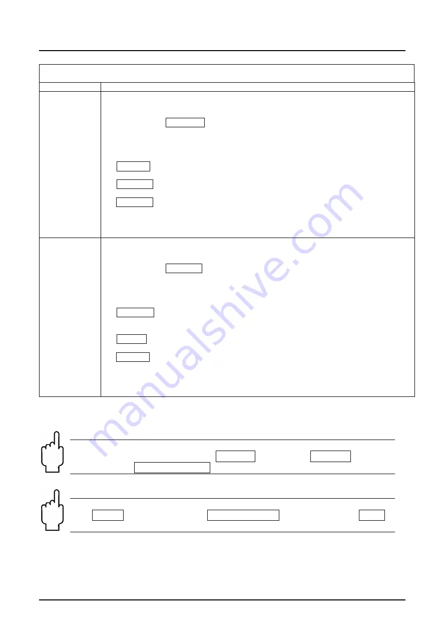
Note: With ZED devices it is necessary to enable the device-specific 
parameter input in the menu Item SecCode in the menu SERVICE in order 
to activate the USER-ABGLEICH function.  


Note: If the new pulse ratio will be used for measurement, than the menu 
item fFaktor in the menu group General Settings must be setted to USER 
calibration. 

Summary of Contents for DF ZL Series

Page 1: ...Operating Instructions for Counter Electronic Model ZED Z or DF ZLxxx or Model ExxR ...

Page 2: ...7 2 Function of the control keys 8 7 3 Character explanation for main menu 9 7 4 General Settings 10 7 5 Flow analogue output and relay 1 12 7 6 Relay 2 and volume counter 15 7 7 User alignment and Service Settings 17 7 8 Error report 20 8 Relay Functions 21 8 1 Switching characteristic limit value 21 8 2 Switching characteristic window 21 9 Technical Information 22 10 Order Codes 23 11 Dimensions...

Page 3: ...o be used maintained and serviced by persons familiar with these operating instructions and in accordance with local regulations applying to Health Safety and prevention of accidents When used in machines the measuring unit should be used only when the machines fulfil the EC machine guidelines 3 Instrument Inspection Instruments are inspected before shipping and sent out in perfect condition Shoul...

Page 4: ...utput is optionally available as current output with 0 4 20 mA or as voltage output with 0 10 V The Parameter names can be shown in the menu in German or English If used where the flow readings change rapidly the display can be pacified and the analogue reading averaged by switching on some software When using analogue output 0 10 V the customer must put a jumper between the terminals 7 and 8 A MI...

Page 5: ...on Don t connect terminal Reset TM GND reset part quantity counter 6 2 DF ZLxxx Model ExxR cable connection Wire number ZED Counter electronics 1 24 VDC 2 GND 3 4 20 mA 0 10 V 4 GND 5 d c 6 Reset TM 7 Relay S1 N O 8 Relay S1 COM 9 Relay S2 N O 10 Relay S2 COM Don t connect terminal Reset TM GND reset part quantity counter ...

Page 6: ...ZED Z page 6 ZED Z K11 0522 6 3 Model ExxR cable connection plug connection Don t connect contact Reset TM GND reset part quantity counter 6 4 Connection example PNP Sensor NPN Sensor ...

Page 7: ...hich lines are marked in the selection matrix in grey colour are available in the respective instrument version Italic written values are blinking in the display if they have been chosen for any input The parameter can only be changed if the security code has been entered correctly The message locked will appear if the input has not been activated analogue output 0 10 V analogue output 0 20 mA ...

Page 8: ...e Press briefly Display min flow value Press for 3 sec Enter switching point for Relay S1 s1SPoint only if parameter SPdirect is set to yes Press briefly Display max flow value Press for 3 sec Enter switching point for Relay S2 s2SPoint only when parameter SPdirect is switched to yes Press for 3 sec Sets min and max value memory to flow value only when parameter fMMReDir is switched to yes RESET P...

Page 9: ...mber by 1 or c Select list value e g L m L h m3 m Press briefly a Select parameter group or parameter or b Increase selected number by 1 or c Select list value e g m3 m L h L m RESET No function in this mode Note If no button is pressed for 20 seconds during parameterising the instrument automatically switches back into measuring mode 7 3 Character explanation for main menu e Button PGM ENTER pres...

Page 10: ...ZED Z page 10 ZED Z K11 0522 7 4 General Settings ...

Page 11: ...alueFS and fUnitFS Attenuation does not function if the switch value is 0 fOverflV Flow overflow value overflow Value in basis is fValueFS and fUnitFS If exceeded an M100 report is generated and faded in alternating with the flow indicator The report is saved and can be reset by briefly pressing the PGM key fFactor Select pulse ration Selection of works calibration or user calibration only for dev...

Page 12: ...ZED Z page 12 ZED Z K11 0522 7 5 Flow analogue output and relay 1 ...

Page 13: ...he keys without using the menu yes direct resetting of the Min Max value memory by simultaneously pressing 3 sec the and keys default no memory reset only possible with fMMRST fMMRST Resets the Min Max flow value memory of the flow indicator yes Resets Min Max value memory for the flow no No action ANALOGUE OUTPUT Menu Item Parameter Function Explanation Values Other aLIFE 0 Select Life Zero Offse...

Page 14: ...e Relay1 Hysteresis Reading is in the same units as the flow indicator only if s1Funct is set to Flow s1FPoint Relay1 Windowpoint Reading is in the same units as the flow indicator only if s1Funct is set to Flow und s1Char auf Window s1SDelay Relay1 Switch delay Delays the switching of the relay when the limit value is exceeded Range _ 0 0 99 9 sec only if s1Funct is set to Flow s1RDelay Relay1 Re...

Page 15: ...ZED Z ZED Z K11 0522 page 15 7 6 Relay 2 and volume counter ...

Page 16: ...Relay2 Hysteresis Reading is in the same units as the flow indicator only if s2Funct is set to Flow s2FPoint Relay2 Windowpoint Reading is in the same units as the flow indicator only if s2Funct is set to Flow and s2Char Is set to Window s2SDelay Relay2 Switch delay Delays the switching of the relay when the limit value is exceeded Range _ 0 0 99 9 sec only if s2Funct is set to Flow s2RDelay Relay...

Page 17: ...lume counter to 0 yes Part volume counter is set to 0 no No action PA0dirct 0 setting option of the part volume counter released using the reset key yes Released default no Blocked TA Unit Measuring units on the total volume indicator mL L m3 gal mgal UU TA 0 Set total volume counter to 0 yes Total volume counter is set to 0 no No action 7 7 User alignment and Service Settings ...

Page 18: ...e menu item CAL Vol the bottom line always shows the current pulse value of the User calibration Calibration process a PulseCnt measures number of impulses e press start counter impulses are counted e press stops counter b Vol Val Enter measured volume value e press c Vol Unit Enter unit for volume value finish with e The pulse value of the User calibration is calculated from these three values an...

Page 19: ...ameters only ZED und Model devices SecCode change Change security code Define or change security code for the first time or change If no code 0000 has been set then the parameter values set are unsecured Save Prm Save parameter record Save current settings Load Prm Load parameter record Restore saved settings reload Restore Default Reset to works default settings Load initial setting with password...

Page 20: ...rect parameter E 161 Value is greater than maximum measuring range value Correct parameter E162 Hysteresis too large Correct parameter E 163 Window point is lower than switching point Correct parameter E242 Frequency must be between 0 2 and 2000 Hz Correct parameter E245 Calculated pulse value out of valid range Correct parameter E300 Error memory value of totalising part counter Keep pressed abou...

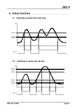
Page 21: ...Z K11 0522 page 21 8 Relay Functions 8 1 Switching characteristic limit value MV REL Sx sxSPoint sxSPoint sxHyste 8 2 Switching characteristic window MV REL Sx sxSPoint sxSPoint sxHyste sxFPoint sxFPoint sxHyste ...

Page 22: ...VA Voltage supply 24 VDC 20 approx 80 mA or 90 250 VAC max 3 VA Analogue output 0 4 20 mA Load max 500 Ω 300 Ω at AC Supply or 0 10 V Load 100kΩ Sensor supply 23 V at 24 VDC max 50 mA 24 V AC supply max 50 mA NAMUR supply 8 2 VDC Ambient temp 20 70 C Dimensions 96 x 96 x 109 mm LxWxD incl screw clamp control panel installation 117 x 117 x 127 mm LxWxD field casing Aperture size 92 0 8 x 92 0 8 mm ...

Page 23: ...M 18 Feldgehäuse 4R 0 A 20 mA 1 R 0 10 V P control panel installation 96x96 mm F field casing 116 x116 mm S field casing with wall mount infinitely variable pivotable R field casing with pipe mounting 24 VDC ZED ZF13 The order details of a ZED electronic in combination with a flow sensor can be found in the data sheet of the measuring device 11 Dimensions ZED Z Control panel ZED Z field housing in...

Page 24: ...instrumentation technology and laboratory use EMC requirements industrial area EN 61010 1 2011 Safety requirements for electrical measuring control and laboratory instruments EN 60529 2014 Protection type housing IP Code Also the following EC guidelines are fulfilled 2014 30 EU EMC Directive 2014 35 EU Low Voltage Directive 2011 65 EU RoHS category 9 industrial monitoring and control instruments c...

Reviews: