NBK-M
6. Mechanical Connection
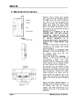
Remove bottom flange from bypass
tube, and insert the cylindrical float in
the NBK bypass tube with the designa-
tion "TOP" at the top. Re-position the
gasket and close the bottom flange
again; firmly tighten the flange bolts.
Mount and tighten the bypass tube to
the vessel to be monitored with process
connection and seal.
Normally it is sufficient to fix the
complete NBK with both process
connections. However should the
NBK be subjected to constant shock
or strong vibrations it is
recommended that the instrument is
secured with rubber-damped pipe
clamps.
To allow for dis-assembly, cleaning and
maintenance, the bypass tube should
never be welded.
Mount and tighten the
magnetic roller
indicator
- if not already mounted - on
the bypass tube with the two
accompanying clamps.
Mount and tighten the
Switches
- if
supplied, on the bypass tube with the
accompanying clamps. The roller
indicators must be loosened so that the
switch clamps can be inserted behind
the roller indicator prior to tightening.
The switches may be adjusted on the
bypass tube to meet the users set point
requirement. The cable connection must
point downwards. Tighten the switch
clamps securely. The switch must be
snug against the bypass tube. The
switch may not function if a gap exists
between the switch housing and bypass
tube.
Mount and tighten
remote sensor
- if
available and not already mounted - on
the bypass tube with the supplied
clamps. The cable terminal box is to
situated at the top of the bypass tube
assembly.
Bottom Flange
Standpipe
Indicator
Float
Roller indicator
Page 6
NBK-M_manual_3-5-04.doc


