


Getting Started
1–3
January 1998
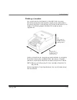
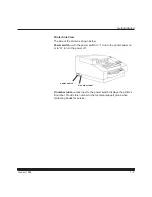
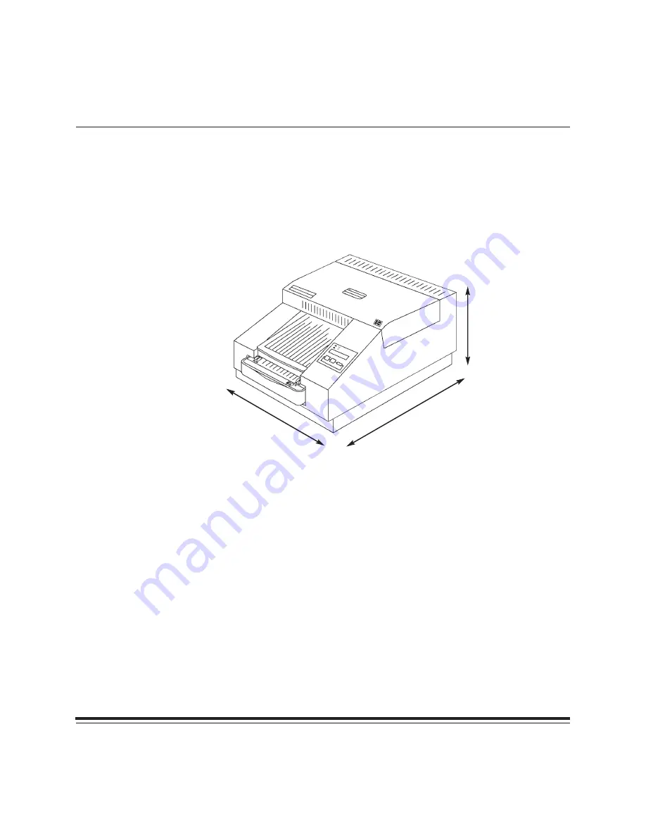
Finding a Location
As you determine the best location for the 8657 Printer, be aware
that certain connections and operations require access behind and on
the side of the printer. You should place the printer so that air flow is not
blocked. The following diagram illustrates the necessary space
requirements.
17
I
12
I
(plan for 20
1
/
4
I
to allow room for
opening cover)
24
I
(plan for 37
1
/
2
I
to allow room for
removing tray)
Airborne dirt particles can cause image quality problems. Avoid placing
the printer in areas where ventilation ducts, open doors, or frequent
passers-by might expose the printer and paper to high levels of debris.
NOTE: Allow two (2) inches (about 5 cm) on all sides of the printer for
easy access.
Refer to Appendix A,
Printer Specifications, for more information about
site requirements.


