Replacements
SM8720-1 – 15APR10
47
Section 5: Replacements
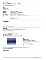
LCD
Prerequisites:
[1]
Do the procedure
“MAIN BOARD, LCD - “Select LCD”” on Page 44
.
[2]
See the
“COVER AYs, BATTERY DOOR AYs and LCD” on Page 9
. Remove:
• BACK COVER AY
• FRONT COVER AY
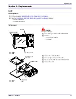
To Remove:
Caution
Dangerous Voltage
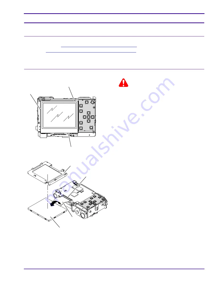
[1]
Do a discharge of the FLASH CAPACITOR.
[2]
Remove:
• 3 SOLDER JOINTS
• SCREW
[3]
Remove the LCD HOLDER.
[4]
Do a complete turnover of the LCD.
[5]
Disconnect the FPC from the CONNECTOR.
[6]
Remove the LCD.
P291_1006AC
SOLDER JOINT
SOLDER JOINT
SCREW
P291_1006ACB
P291_1007AC
P291_1007ACA
MONITOR LCD
HOLDER
MONITOR
LCD
FPC
CONNECTOR
Summary of Contents for C140 - EASYSHARE Digital Camera
Page 67: ...Diagrams SM8720 1 15APR10 67 Section 7 Diagrams System Connections ...
Page 69: ...Diagrams SM8720 1 15APR10 69 MAIN BOARD 2 of 8 MAIN BOARD 2 of 8 P323_0006FC_ ...
Page 70: ...SERVICE MANUAL 70 15APR10 SM8720 1 MAIN BOARD 3 of 8 P323_0007FC_ MAIN BOARD 3 of 8 ...
Page 71: ...Diagrams SM8720 1 15APR10 71 MAIN BOARD 4 of 8 P323_0008FC_ MAIN BOARD 4 of 8 ...
Page 72: ...SERVICE MANUAL 72 15APR10 SM8720 1 MAIN BOARD 5 of 8 MAIN BOARD 5 of 8 P323_0009FC_ ...
Page 73: ...Diagrams SM8720 1 15APR10 73 MAIN BOARD 6 of 8 P323_0010FC_ MAIN BOARD 6 of 8 ...
Page 74: ...SERVICE MANUAL 74 15APR10 SM8720 1 MAIN BOARD 7 of 8 P323_0011FC_ MAIN BOARD 7 of 8 ...
Page 75: ...Diagrams SM8720 1 15APR10 75 MAIN BOARD 8 of 8 P323_0012FC_ MAIN BOARD 8 of 8 ...
Page 77: ...Diagrams SM8720 1 15APR10 77 STROBE BOARD 3 of 3 P323_0015HC_ STROBE BOARD 3 of 3 ...
Page 79: ...Diagrams SM8720 1 15APR10 79 MAIN BOARD Bottom MAIN BOARD Bottom P323_0001HC_ ...

